API-Reference
Parametric Shapes
Rotated Shapes
RotateStraightShape()
- class RotateStraightShape(rotation_angle=360.0, color=(0.89, 0.101, 0.109), name='rotatestraightshape', **kwargs)
Bases:
RotateMixedShapeRotates a 3d CadQuery solid from points connected with straight connections.
- Parameters:
rotation_angle – The rotation angle to use when revolving the solid (degrees).
color – the color to use when exporting the shape to CAD formats that support color. A tuple of three floats each ranging between 0 and 1.
name – the name of the shape, used to name files when exporting and as a legend in plots.
translate – distance to translate / move the shape by. Specified as a vector of (X,Y,Z) directions.
RotateSplineShape()
- class RotateSplineShape(rotation_angle=360.0, color=(0.415, 0.239, 0.603), name='rotatesplineshape', **kwargs)
Bases:
RotateMixedShapeRotates a 3d CadQuery solid from points connected with splines.
- Parameters:
rotation_angle – The rotation_angle to use when revolving the solid. Defaults to 360.0.
color – the color to use when exporting the shape to CAD formats that support color. A tuple of three floats each ranging between 0 and 1.
name – the name of the shape, used to name files when exporting and as a legend in plots.
translate – distance to translate / move the shape by. Specified as a vector of (X,Y,Z) directions.
RotateMixedShape()
- class RotateMixedShape(rotation_angle=360.0, color=(0.121, 0.47, 0.705), name='rotatemixedshape', translate=None, **kwargs)
Bases:
ShapeRotates a 3d CadQuery solid from points connected with a mixture of straight lines and splines.
- Parameters:
rotation_angle – The rotation_angle to use when revolving the solid (degrees). Defaults to 360.0.
color – the color to use when exporting the shape to CAD formats that support color. A tuple of three floats each ranging between 0 and 1.
name – the name of the shape, used to name files when exporting and as a legend in plots.
translate – distance to translate / move the shape by. Specified as a vector of (X,Y,Z) directions.
- create_solid()
Creates a rotated 3d solid using points with straight and spline edges.
- Returns:
A CadQuery solid: A 3D solid volume
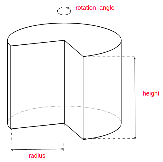
RotateCircleShape()
- class RotateCircleShape(radius, rotation_angle=360.0, color=(1.0, 1.0, 0.6), name='rotatecircleshape', translate=None, **kwargs)
Bases:
ShapeRotates a circular 3d CadQuery solid from a central point and a radius
- Parameters:
radius – radius of the shape
rotation_angle – The rotation_angle to use when revolving the solid (degrees). Defaults to 360.0.
color – the color to use when exporting the shape to CAD formats that support color. A tuple of three floats each ranging between 0 and 1.
name – the name of the shape, used to name files when exporting and as a legend in plots.
translate – distance to translate / move the shape by. Specified as a vector of (X,Y,Z) directions.
- create_solid()
Creates a rotated 3d solid using points with circular edges.
- Returns:
A 3D solid volume
- Return type:
A CadQuery solid
Extruded Shapes
ExtrudeStraightShape()
- class ExtrudeStraightShape(distance, color=(1.0, 0.498, 0.0), name='extrudestraightshape', **kwargs)
Bases:
ExtrudeMixedShapeExtrudes a 3d CadQuery solid from points connected with straight lines.
- Parameters:
distance – the extrusion distance to use
color – the color to use when exporting the shape to CAD formats that support color. A tuple of three floats each ranging between 0 and 1.
name – the name of the shape, used to name files when exporting and as a legend in plots.
translate – distance to translate / move the shape by. Specified as a vector of (X,Y,Z) directions.
ExtrudeSplineShape()
- class ExtrudeSplineShape(distance, color=(0.984, 0.603, 0.6), name='extrudesplineshape', **kwargs)
Bases:
ExtrudeMixedShapeExtrudes a 3d CadQuery solid from points connected with spline connections.
- Parameters:
distance – the extrusion distance to use
color – the color to use when exporting the shape to CAD formats that support color. A tuple of three floats each ranging between 0 and 1.
name – the name of the shape, used to name files when exporting and as a legend in plots.
translate – distance to translate / move the shape by. Specified as a vector of (X,Y,Z) directions.
ExtrudeMixedShape()
- class ExtrudeMixedShape(distance, extrude_both=True, rotation_angle=360.0, extrusion_start_offset=0.0, color=(0.2, 0.627, 0.172), name='extrudemixedshape', translate=None, **kwargs)
Bases:
ShapeExtrudes a 3d CadQuery solid from points connected with a mixture of straight and spline connections.
- Parameters:
distance – the extrusion distance to use
extrude_both – If set to True, the extrusion will occur in both directions. Defaults to True.
rotation_angle – rotation angle of solid created. A cut is performed from rotation_angle to 360 degrees. Defaults to 360.0.
extrusion_start_offset –
color – the color to use when exporting the shape to CAD formats that support color. A tuple of three floats each ranging between 0 and 1.
name – the name of the shape, used to name files when exporting and as a legend in plots.
translate – distance to translate / move the shape by. Specified as a vector of (X,Y,Z) directions.
- create_solid()
Creates an extruded 3d solid using points connected with straight and spline edges.
- Returns:
A CadQuery solid: A 3D solid volume
ExtrudeCircleShape()
- class ExtrudeCircleShape(distance, radius, extrusion_start_offset=0.0, rotation_angle=360, extrude_both=True, color=(0.984, 0.603, 0.6), name='extrudecircleshape', translate=None, **kwargs)
Bases:
ShapeExtrudes a circular 3d CadQuery solid from a central point and a radius
- Parameters:
distance – the extrusion distance to use
radius – radius of the shape.
extrusion_start_offset –
rotation_angle – rotation_angle of solid created. a cut is performed from rotation_angle to 360 degrees. Defaults to 360.
extrude_both – if set to True, the extrusion will occur in both directions. Defaults to True.
color – the color to use when exporting the shape to CAD formats that support color. A tuple of three floats each ranging between 0 and 1.
name – the name of the shape, used to name files when exporting and as a legend in plots.
translate – distance to translate / move the shape by. Specified as a vector of (X,Y,Z) directions.
- create_solid()
Creates a extruded 3d solid using points with circular edges.
- Returns:
A 3D solid volume
- Return type:
A CadQuery solid
Swept Shapes
SweepStraightShape()
- class SweepStraightShape(path_points, workplane='XY', path_workplane='XZ', force_cross_section=False, color=(0.698, 0.8745, 0.541), name='sweepstraightshape', **kwargs)
Bases:
SweepMixedShapeSweeps a 2D shape created from points connected with straight lines along a defined spline path to create a 3D CadQuery solid. Note, some variation in the cross-section of the solid may occur.
- Parameters:
path_points – A list of XY, YZ or XZ coordinates connected by spline connections which define the path along which the 2D shape is swept
workplane – Workplane in which the 2D shape to be swept is defined. Defaults to “XY”.
path_workplane – Workplane in which the spline path is defined. Defaults to “XZ”.
force_cross_section – If True, cross-section of solid is forced to be shape defined by points in workplane at each path_point. Defaults to False.
color – the color to use when exporting the shape to CAD formats that support color. A tuple of three floats each ranging between 0 and 1.
name – the name of the shape, used to name files when exporting and as a legend in plots.
translate – distance to translate / move the shape by. Specified as a vector of (X,Y,Z) directions.
SweepSplineShape()
- class SweepSplineShape(path_points, workplane='XY', path_workplane='XZ', force_cross_section=False, color=(0.992, 0.749, 0.435), name='sweepsplineshape', **kwargs)
Bases:
SweepMixedShapeSweeps a 2D shape created from points connected with spline connections along a defined spline path to create a 3D CadQuery solid. Note, some variation in the cross-section of the solid may occur.
- Parameters:
path_points – A list of XY, YZ or XZ coordinates connected by spline connections which define the path along which the 2D shape is swept.
workplane – Workplane in which the 2D shape to be swept is defined. Defaults to “XY”.
path_workplane – Workplane in which the spline path is defined. Defaults to “XZ”.
force_cross_section (bool, optional) – If True, cross-setion of solid is forced to be shape defined by points in workplane at each path_point. Defaults to False.
color – the color to use when exporting the shape to CAD formats that support color. A tuple of three floats each ranging between 0 and 1.
name – the name of the shape, used to name files when exporting and as a legend in plots.
translate – distance to translate / move the shape by. Specified as a vector of (X,Y,Z) directions.
SweepMixedShape()
- class SweepMixedShape(path_points, workplane='XY', path_workplane='XZ', force_cross_section=False, color=(0.792, 0.698, 0.839), name='sweepmixedshape', translate=None, **kwargs)
Bases:
ShapeSweeps a 2D shape created from points connected with straight, spline or circle connections along a defined spline path to create a 3D CadQuery solid. Note, some variation in cross-section of the solid may occur.
- Parameters:
path_points – A list of XY, YZ or XZ coordinates connected by spline connections which define the path along which the 2D shape is swept.
workplane – Workplane in which the 2D shape to be swept is defined. Defaults to “XY”.
path_workplane – Workplane in which the spline path is defined. Defaults to “XZ”.
force_cross_section (bool, optional) – If True, cross-section of solid is forced to be shape defined by points in workplane at each path_point. Defaults to False.
color – the color to use when exporting the shape to CAD formats that support color. A tuple of three floats each ranging between 0 and 1.
name – the name of the shape, used to name files when exporting and as a legend in plots.
translate – distance to translate / move the shape by. Specified as a vector of (X,Y,Z) directions.
- create_solid()
Creates a swept 3D solid from a 2D shape with mixed connections.
- Returns:
A 3D solid volume
- Return type:
A CadQuery solid
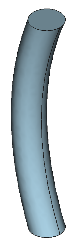
SweepCircleShape()
- class SweepCircleShape(radius, path_points, workplane='XY', path_workplane='XZ', force_cross_section=False, color=(0.651, 0.808, 0.89), name='sweepcircleshape', translate=None, **kwargs)
Bases:
ShapeSweeps a 2D circle of a defined radius along a defined spline path to create a 3D CadQuery solid. Note, some variation in the cross-section of the solid may occur.
- Parameters:
radius – Radius of 2D circle to be swept.
path_points – A list of XY, YZ or XZ coordinates connected by spline connections which define the path along which the 2D shape is swept
workplane – Workplane in which the circle to be swept is defined. Defaults to “XY”.
path_workplane – Workplane in which the spline path is defined. Defaults to “XZ”.
force_cross_section – If True, cross-section of solid is forced to be shape defined by points in workplane at each path_point. Defaults to False.
color – the color to use when exporting the shape to CAD formats that support color. A tuple of three floats each ranging between 0 and 1.
name – the name of the shape, used to name files when exporting and as a legend in plots.
translate – distance to translate / move the shape by. Specified as a vector of (X,Y,Z) directions.
- create_solid()
Creates a swept 3D solid from a 2D circle.
- Returns:
A 3D solid volume
- Return type:
A CadQuery solid
Parametric Components
These are components that represent a selection of the components found in fusion reactors and are created from parameters. These components all inherit from the parametric Shape classes.
Blankets
BlanketConstantThicknessArcH()

- class BlanketConstantThicknessArcH(inner_mid_point, inner_upper_point, inner_lower_point, thickness, **kwargs)
Bases:
RotateMixedShapeAn outboard blanket volume that follows the curvature of a circular arc and a constant blanket thickness. The upper and lower edges continue horizontally for the thickness of the blanket to back of the blanket.
- Parameters:
inner_mid_point – the x,z coordinates of the mid point on the inner surface of the blanket.
inner_upper_point – the x,z coordinates of the upper point on the inner surface of the blanket.
inner_lower_point – the x,z coordinates of the lower point on the inner surface of the blanket.
thickness – the radial thickness of the blanket in cm.
- find_points()
Calculates the shape points. Empty method which some components overright when inheritting.
BlanketConstantThicknessArcV()

- class BlanketConstantThicknessArcV(inner_mid_point, inner_upper_point, inner_lower_point, thickness, **kwargs)
Bases:
RotateMixedShapeAn outboard blanket volume that follows the curvature of a circular arc and a constant blanket thickness. The upper and lower edges continue vertically for the thickness of the blanket to back of the blanket.
- Parameters:
inner_mid_point – the x,z coordinates of the mid point on the inner surface of the blanket.
inner_upper_point – the x,z coordinates of the upper point on the inner surface of the blanket.
inner_lower_point – the x,z coordinates of the lower point on the inner surface of the blanket.
thickness – the radial thickness of the blanket in cm.
- find_points()
Calculates the shape points. Empty method which some components overright when inheritting.
BlanketFP()

- class BlanketFP(thickness, start_angle, stop_angle, plasma=None, minor_radius=150.0, major_radius=450.0, triangularity=0.55, elongation=2.0, vertical_displacement=0.0, offset_from_plasma=0.0, num_points=50, allow_overlapping_shape=False, **kwargs)
Bases:
RotateMixedShapeA blanket volume created from plasma parameters. In might be nessecary to increase the num_points when making long but thin geometry with this component.
- Parameters:
thickness (float or [float] or callable or [(float), (float)]) – the thickness of the blanket (cm). If the thickness is a float then this produces a blanket of constant thickness. If the thickness is a tuple of floats, blanket thickness will vary linearly between the two values. If thickness is callable, then the blanket thickness will be a function of poloidal angle (in degrees). If thickness is a list of two lists (thicknesses and angles) then these will be used together with linear interpolation.
start_angle – the angle in degrees to start the blanket, measured anti clockwise from 3 o’clock.
stop_angle – the angle in degrees to stop the blanket, measured anti clockwise from 3 o’clock.
plasma – If not None, the parameters of the plasma Object will be used.
minor_radius – the minor radius of the plasma (cm).
major_radius – the major radius of the plasma (cm).
triangularity – the triangularity of the plasma.
elongation – the elongation of the plasma.
vertical_displacement – the vertical_displacement of the plasma (cm).
offset_from_plasma – the distance between the plasma and the blanket (cm). If float, constant offset. If list of floats, offset will vary linearly between the values. If callable, offset will be a function of poloidal angle (in degrees). If a list of two lists (angles and offsets) then these will be used together with linear interpolation.
num_points – number of points that will describe the shape.
- create_offset_points(thetas, offset)
generates a list of points following parametric equations with an offset
- Parameters:
thetas (np.array) – the angles in degrees.
offset (callable) – offset value (cm). offset=0 will follow the parametric equations.
- Returns:
list of points [[R1, Z1, connection1], [R2, Z2, connection2], …]
- Return type:
list
- distribution(theta, pkg=<module 'numpy' from '/home/docs/checkouts/readthedocs.org/user_builds/paramak/conda/main/lib/python3.9/site-packages/numpy/__init__.py'>)
Plasma distribution theta in degrees
- Parameters:
theta (float or np.array or sp.Symbol) – the angle(s) in degrees.
pkg (module, optional) – Module to use in the funciton. If sp, as sympy object will be returned. If np, a np.array or a float will be returned. Defaults to np.
- Returns:
- (float, float) or (sympy.Add, sympy.Mul) or
(numpy.array, numpy.array): The R and Z coordinates of the point with angle theta
- find_points(angles=None)
Calculates the shape points. Empty method which some components overright when inheritting.
- make_callable(attribute)
This function transforms an attribute (thickness or offset) into a callable function of theta
BlanketFPPoloidalSegments()

- class BlanketFPPoloidalSegments(segments_angles=None, num_segments=7, length_limits=None, nb_segments_limits=None, segments_gap=0.0, **kwargs)
Bases:
BlanketFPPoloidally segmented Blanket inheriting from paramak.BlanketFP.
- Parameters:
segments_angles – If not None, the segments ends will be located at these angles. If None and if the constraints length_limits and nb_segments_limits are not None, segments angles will be linearly distributed. Else, an optimum configuration meeting the set requirements will be found. Defaults to None.
num_segments – Number of segments (ignored if segments_angles is not None).
length_limits – The minimum and maximum acceptable length of the segments. Ex: (100, 500), (100, None), (None, 300), None, (None, None).
nb_segments_limits – The minimum and maximum acceptable number of segments. Ex: (3, 10), (5, None), (None, 7), None, (None, None).
segments_gap – Distance between segments.
- create_segment_cutters()
Creates a shape for cutting the blanket into segments and store it in segments_cutter attribute
- create_solid()
Creates a rotated 3d solid using points with straight and spline edges.
- Returns:
A CadQuery solid: A 3D solid volume
- find_points()
Calculates the shape points. Empty method which some components overright when inheritting.
- get_angles()
Get the poloidal angles of the segments.
- Returns:
the angles
- Return type:
list
- compute_lengths_from_angles(angles, distribution)
Computes the length of segments between a set of points on a (x,y) distribution.
- Parameters:
angles – Contains the angles of the points (degrees)
distribution – function taking an angle as argument and returning (x,y) coordinates.
- Returns:
contains the lengths of the segments.
- Return type:
list
- segments_optimiser(length_limits, nb_segments_limits, distribution, angles, stop_on_success=True)
Optimiser segmenting a given R(theta), Z(theta) distribution of points with constraints regarding the number of segments and the length of the segments.
- Parameters:
length_limits ((float, float)) – The minimum and maximum acceptable length of the segments. Ex: (100, 500), (100, None), (None, 300), None, (None, None)
nb_segments_limits ((int, int)) – The minimum and maximum acceptable number of segments. Ex: (3, 10), (5, None), (None, 7), None, (None, None)
distribution (callable) – function taking an angle as argument and returning (x,y) coordinates.
angles ((float, float)) – the start and stop angles of the distribution.
stop_on_sucess (bool, optional) – If set to True, the optimiser will stop as soon as a configuration meets the requirements.
- Returns:
list of optimised angles
- Return type:
list
Blanket Cutting Tools
BlanketCutterParallels()

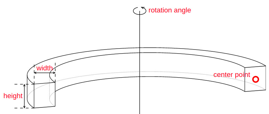
- class BlanketCutterParallels(thickness, gap_size, height=2000.0, width=2000.0, azimuth_placement_angle=[0.0, 36.0, 72.0, 108.0, 144.0, 180.0, 216.0, 252.0, 288.0, 324.0], name='blanket_cutter_parallels', **kwargs)
Bases:
ExtrudeStraightShapeCreates an extruded shape with a parallel rectangular section repeated around the reactor. The shape is used to cut other components (eg. blankets and firstwalls) in order to create a banana section of the blankets with parallel sides.Typically used to divide a blanket into vertical sections with a fixed distance between each section.
- Parameters:
thickness – extruded distance (cm) of the cutter which translates to being the gap size between blankets when the cutter is used to segment blankets.
gap_size – the distance between the inner edges of the two parallel extrusions
height – height (cm) of the port. Defaults to 2000.0.
width – width (cm) of the port. Defaults to 2000.0.
name – Defaults to “blanket_cutter_Parallels”.
azimuth_placement_angle (float or list of floats) – Defaults to [0., 36., 72., 108., 144., 180., 216., 252., 288., 324.].
- create_solid()
Creates an extruded 3d solid using points connected with straight and spline edges.
- Returns:
A CadQuery solid: A 3D solid volume
- find_points()
Calculates the shape points. Empty method which some components overright when inheritting.
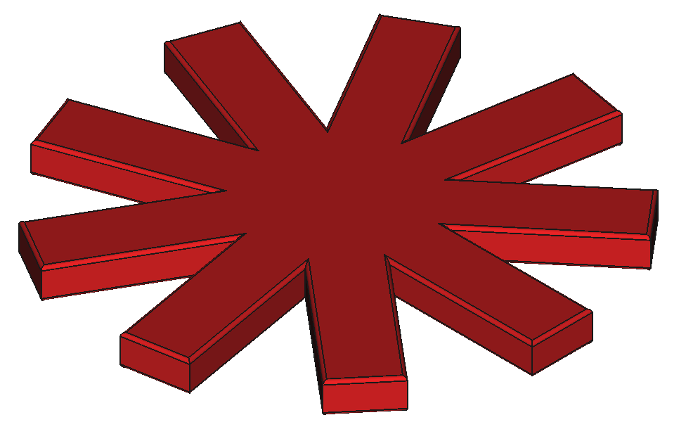
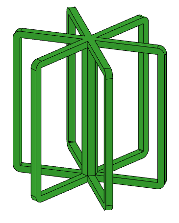
BlanketCutterStar()

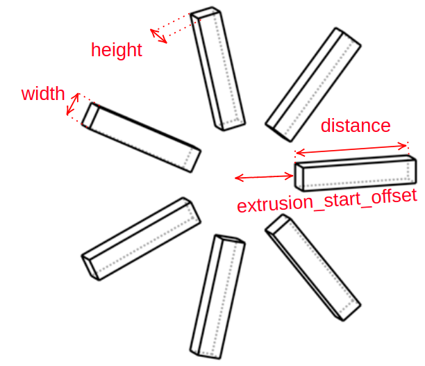
- class BlanketCutterStar(distance, height=2000.0, width=2000.0, azimuth_placement_angle=[0.0, 36.0, 72.0, 108.0, 144.0, 180.0, 216.0, 252.0, 288.0, 324.0], name='blanket_cutter_star', **kwargs)
Bases:
ExtrudeStraightShapeCreates an extruded shape with a rectangular section that is used to cut other components (eg. blankets and firstwalls) in order to create banana style blanket segments. Typically used to divide a blanket into vertical sections with a fixed gap between each section.
- Parameters:
distance – extruded distance (cm) of the cutter which translates to being the gap size between blankets when the cutter is used to segment blankets.
height – height (cm) of the port. Defaults to 2000.0.
width – width (cm) of the port. Defaults to 2000.0.
azimuth_placement_angle (list or float, optional) – Defaults to [0., 36., 72., 108., 144., 180., 216., 252., 288., 324.]
name – defaults to “blanket_cutter_star”.
- find_points()
Calculates the shape points. Empty method which some components overright when inheritting.
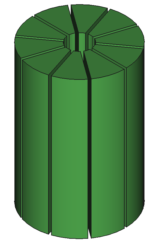
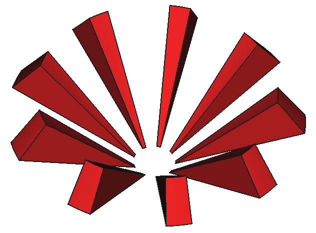
PoloidalSegmenter()

- class PoloidalSegments(center_point, shape_to_segment=None, number_of_segments=10, max_distance_from_center=1000.0, name='poloidal_segmenter', **kwargs)
Bases:
RotateStraightShapeCreates a ring of wedges from a central point. When provided with a shape_to_segment the shape will be segmented by the wedges. This is useful for segmenting geometry into equal poloidal angles. Intended to segment the firstwall geometry for using in neutron wall loading simulations.
- Parameters:
center_point – the center of the segmentation wedges (x,z) values (cm).
shape_to_segment – the Shape to segment, if None then the segmenting solids will be returned. Defaults to None.
number_of_segments (int, optional) – the number of equal angles segments in 360 degrees. Defaults to 10.
max_distance_from_center (float) – the maximum distance from the center point outwards (cm). Defaults to 1000.0.
name (str, optional) – defaults to “poloidal_segmenter”.
- create_solid()
Creates a 3d solid using points with straight edges. Individual solids in the compound can be accessed using .Solids()[i] where i is an int.
- Returns:
A CadQuery solid: A 3D solid volume
- find_points()
Finds the XZ points joined by straight connections that describe the 2D profile of the poloidal segmentation shape.
Center Columns
CenterColumnShieldCylinder()
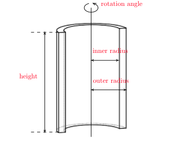
- class CenterColumnShieldCylinder(height, inner_radius, outer_radius, center_height=0.0, name='CenterColumnShieldCylinder', color=(0.0, 0.333, 0.0), **kwargs)
Bases:
RotateStraightShapeA cylindrical center column shield volume with constant thickness.
- Parameters:
height – height of the center column shield.
inner_radius – the inner radius of the center column shield.
outer_radius – the outer radius of the center column shield.
center_height – the vertical height of the center of the component.
- find_points()
Finds the XZ points joined by straight connections that describe the 2D profile of the center column shield shape.
CenterColumnShieldHyperbola()

- class CenterColumnShieldHyperbola(height, inner_radius, mid_radius, outer_radius, name='center_column', color=(0.0, 0.333, 0.0), **kwargs)
Bases:
RotateMixedShapeA center column shield volume with a hyperbolic outer profile and constant cylindrical inner profile.
- Parameters:
height – height of the center column shield.
inner_radius – the inner radius of the center column shield.
mid_radius – the inner radius of the outer hyperbolic profile of the center column shield.
outer_radius – the outer radius of the center column shield.
name – Defaults to “center_column”.
- find_points()
Finds the XZ points and connection types (straight and spline) that describe the 2D profile of the center column shield shape.
CenterColumnShieldFlatTopHyperbola()

- class CenterColumnShieldFlatTopHyperbola(height, arc_height, inner_radius, mid_radius, outer_radius, name='center_column', color=(0.0, 0.333, 0.0), **kwargs)
Bases:
RotateMixedShapeA center column shield volume with a hyperbolic outer profile joined to flat profiles at the top and bottom of the shield, and a constant cylindrical inner profile.
- Parameters:
height – height of the center column shield.
arc_height – height of the outer hyperbolic profile of the center column shield.
inner_radius – the inner radius of the center column shield.
mid_radius – the inner radius of the outer hyperbolic profile of the center column shield.
outer_radius – the outer_radius of the center column shield.
name – Defaults to “center_column”.
- find_points()
Finds the XZ points and connection types (straight and spline) that describe the 2D profile of the center column shield shape.
CenterColumnShieldFlatTopCircular()

- class CenterColumnShieldFlatTopCircular(height, arc_height, inner_radius, mid_radius, outer_radius, name='center_column', color=(0.0, 0.333, 0.0), **kwargs)
Bases:
RotateMixedShapeA center column shield volume with a circular outer profile joined to flat profiles at the top and bottom of the shield, and a constant cylindrical inner profile.
- Parameters:
height – height of the center column shield.
arc_height – height of the outer circular profile of the center column shield.
inner_radius – the inner radius of the center column shield.
mid_radius – the inner radius of the outer circular profile of the center column shield.
outer_radius – the outer radius of the center column shield.
name – Defaults to “center_column”.
- find_points()
Finds the XZ points and connection types (straight and circle) that describe the 2D profile of the center column shield shape.
CenterColumnShieldPlasmaHyperbola()

- class CenterColumnShieldPlasmaHyperbola(height, inner_radius, mid_offset, edge_offset, major_radius=450.0, minor_radius=150.0, triangularity=0.55, elongation=2.0, **kwargs)
Bases:
RotateMixedShapeA center column shield volume with a curvature controlled by the shape of the plasma and offsets specified at the plasma center and edges. Shield thickness is controlled by the relative values of the shield offsets and inner radius.
- Parameters:
height – height of the center column shield.
inner_radius – the inner radius of the center column shield.
mid_offset – the offset of the shield from the plasma at the plasma center.
edge_offset – the offset of the shield from the plasma at the plasma edge.
major_radius – the major radius of the plasma. Defaults to 450.0.
minor_radius – the minor radius of the plasma. Defaults to 150.0.
triangularity – the triangularity of the plasma. Defaults to 0.55.
elongation – the elongation of the plasma. Defaults to 2.0.
- find_points()
Finds the XZ points and connection types (straight and spline) that describe the 2D profile of the center column shield shape.
InboardFirstwallFCCS()

- class InboardFirstwallFCCS(central_column_shield, thickness, color=(0.5, 0.5, 0.5), **kwargs)
Bases:
RotateMixedShapeAn inboard firstwall component that builds a constant thickness layer from the central column shield. The center column shields can be of type: CenterColumnShieldCylinder, CenterColumnShieldHyperbola, CenterColumnShieldFlatTopHyperbola, CenterColumnShieldCircular, CenterColumnShieldPlasmaHyperbola or CenterColumnShieldFlatTopCircular
- Parameters:
central_column_shield – The central column shield object to build from
thickness – the radial thickness of the firstwall (cm)
- find_points()
Calculates the shape points. Empty method which some components overright when inheritting.
Coolant Channels
CoolantChannelRingStraight()

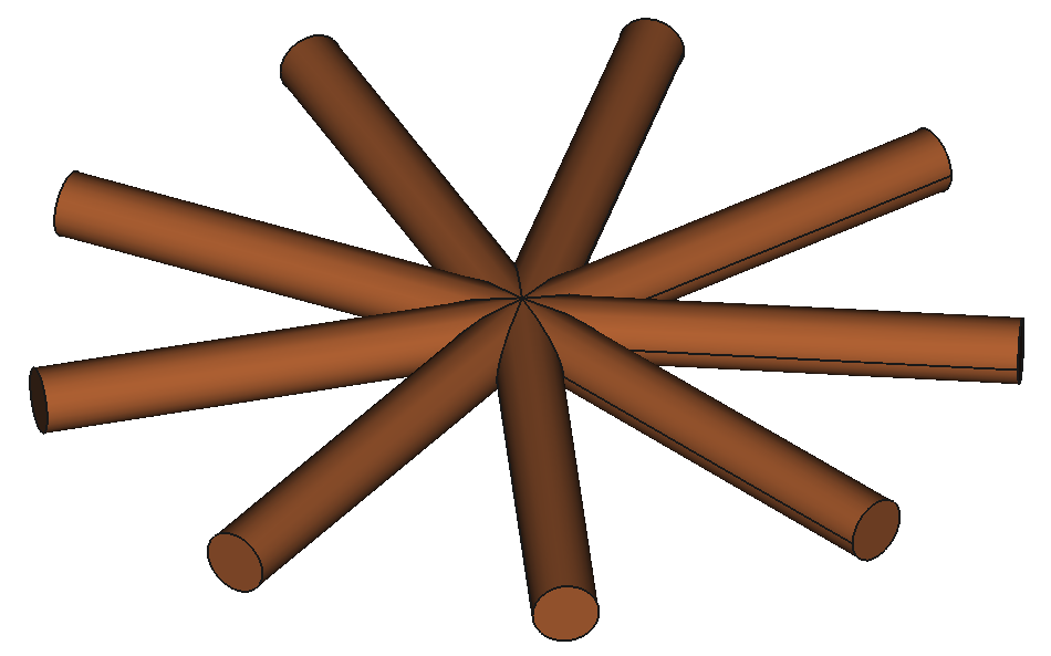
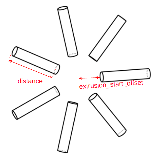
- class CoolantChannelRingStraight(height, channel_radius, number_of_coolant_channels, ring_radius, start_angle=0.0, **kwargs)
Bases:
ExtrudeCircleShapeA ring of equally-spaced straight circular coolant channels with constant thickness.
- Parameters:
height – height of each coolant channel in ring.
channel_radius – radius of each coolant channel in ring.
number_of_coolant_channels – number of coolant channels in ring.
radius (ring) – radius of coolant channel ring.
start_angle – angle at which the first channel in the ring is placed. Defaults to 0.0.
rotation_axis (str, optional) – azimuthal axis around which the separate coolant channels are placed.
workplane (str, optional) – plane in which the cross-sections of the coolant channels lie. Defaults to “XY”.
- find_azimuth_placement_angle()
Calculates the azimuth placement angles based on the number of coolant channels.
- find_points()
Calculates the shape points. Empty method which some components overright when inheritting.
CoolantChannelRingCurved()


- class CoolantChannelRingCurved(height, channel_radius, number_of_coolant_channels, ring_radius, mid_offset, start_angle=0.0, **kwargs)
Bases:
SweepCircleShapeA ring of equally-spaced curved circular coolant channels with constant thickness.
- Parameters:
height – height of each coolant channel in ring.
channel_radius – radius of each coolant channel in ring.
number_of_coolant_channels – number of coolant channels in ring.
ring_radius – radius of coolant channel ring.
start_angle – angle at which the first channel in the ring is placed. Defaults to 0.0.
rotation_axis – azimuthal axis around which the separate coolant channels are placed. Default calculated by workplane and path_workplane.
workplane (str, optional) – plane in which the cross-sections of the coolant channels lie. Defaults to “XY”.
path_workplane (str, optional) – plane in which the cross-sections of the coolant channels are swept. Defaults to “XZ”.
force_cross_section (bool, optional) – forces coolant channels to have a more constant cross-section along their curve. Defaults to False.
- find_azimuth_placement_angle()
Calculates the azimuth placement angles based on the number of coolant channels.
Cutting Tools
CuttingWedge()

- class CuttingWedge(height, radius, rotation_angle=180.0, **kwargs)
Bases:
RotateStraightShapeCreates a wedge from height, radius and rotation angle arguments than can be useful for cutting sector models.
- Parameters:
height – the vertical (z axis) height of the coil (cm).
radius – the horizontal (x axis) width of the coil (cm).
rotation_angle – Defaults to 180.0.
- find_points()
Calculates the shape points. Empty method which some components overright when inheritting.
CuttingWedgeFS()
- class CuttingWedgeFS(shape, **kwargs)
Bases:
CuttingWedgeCreates a wedge from a Shape that can be useful for cutting sector models.
- Parameters:
shape (paramak.Shape) – a paramak.Shape object that is used to find the height and radius of the wedge
Divertors
ITERtypeDivertor()

- class ITERtypeDivertor(anchors=((450, -300), (561, -367)), coverages=(90, 180), radii=(50, 25), lengths=(78, 87), dome=True, dome_height=43, dome_length=66, dome_thickness=10, dome_pos=0.5, tilts=(-27, 0), **kwargs)
Bases:
RotateMixedShapeCreates an ITER-like divertor with inner and outer vertical targets and dome
- Parameters:
anchors – xz coordinates of points at the top of vertical targets.
coverages – coverages (anticlockwise) in degrees of the circular parts of vertical targets.
radii – radii (cm) of circular parts of the vertical targets.
lengths – leg length (cm) of the vertical targets.
dome – if set to False, the dome will not be created.
dome_height – distance (cm) between the dome base and lower points.
dome_length – length of the dome.
dome_thickness – thickness of the dome.
dome_pos – relative location of the dome between vertical targets (0 inner, 1 outer). Ex: 0.5 will place the dome in between the targets.
tilts ((float, float), optional) – tilt angles (anticlockwise) in degrees for the vertical targets.
- find_points()
Finds the XZ points and connection types (straight and circle) that describe the 2D profile of the ITER-like divertor
ITERtypeDivertorNoDome()

- class ITERtypeDivertorNoDome(**kwargs)
Bases:
ITERtypeDivertorCreates an ITER-like divertor with inner and outer vertical targets
Inner Toroidal Field Coils
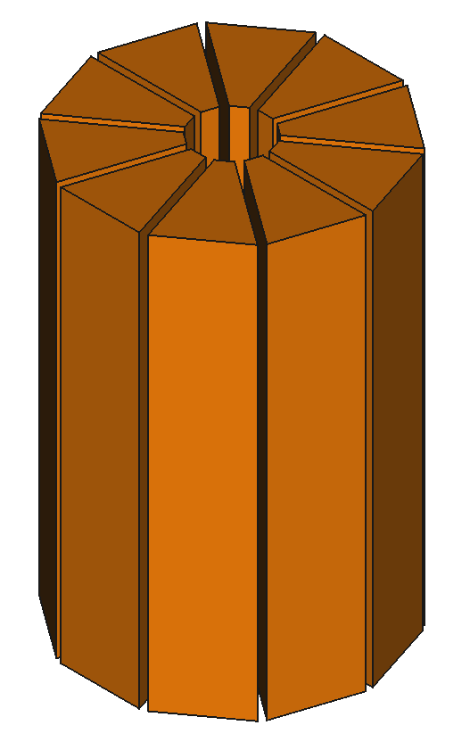
InnerTfCoilsCircular()
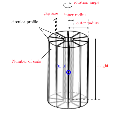
- class InnerTfCoilsCircular(height, inner_radius, outer_radius, number_of_coils, gap_size, azimuth_start_angle=0.0, workplane='XY', rotation_axis='Z', **kwargs)
Bases:
ExtrudeMixedShapeA tf coil volume with cylindrical inner and outer profiles and constant gaps between each coil.
- Parameters:
height – height of tf coils.
inner_radius – inner radius of tf coils.
outer_radius – outer radius of tf coils.
number_of_coils – number of tf coils.
gap_size – gap between adjacent tf coils.
azimuth_start_angle – Defaults to 0.0.
workplane – Defaults to “XY”.
rotation_axis – Defaults to “Z”.
- find_azimuth_placement_angle()
Calculates the azimuth placement angles based on the number of tf coils
- find_points()
Finds the points that describe the 2D profile of the tf coil shape
InnerTfCoilsFlat()
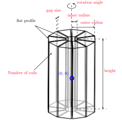
- class InnerTfCoilsFlat(height, inner_radius, outer_radius, number_of_coils, gap_size, radius_type='corner', azimuth_start_angle=0.0, workplane='XY', rotation_axis='Z', **kwargs)
Bases:
ExtrudeStraightShapeA tf coil volume with straight inner and outer profiles and constant gaps between each coil. Note: the inner / outer surface is not equal distance to the center point everywhere as the corners are further than the straight sections.
- Parameters:
height – height of tf coils.
inner_radius – Distance between center point and the inner surface of the tf coils.
outer_radius – Distance between center point and the outer surface of the tf coils.
number_of_coils – number of tf coils.
gap_size – gap between adjacent tf coils.
radius_type – Controls the part of the inner surface used when defining the inner_radius and outer_radius. Can be set to either ‘corner’ or ‘straight’.
azimuth_start_angle – defaults to 0.0.
workplane – defaults to “XY”.
rotation_axis – Defaults to “Z”.
- find_azimuth_placement_angle()
Calculates the azimuth placement angles based on the number of tf coils
- find_points()
Finds the points that describe the 2D profile of the tf coil shape
Poloidal Field coils
PoloidalFieldCoil()
- class PoloidalFieldCoil(height, width, center_point, name='pf_coil', **kwargs)
Bases:
RotateStraightShapeCreates a rectangular poloidal field coil.
- Parameters:
height – the vertical (z axis) height of the coil (cm).
width – the horizontal (x axis) width of the coil (cm).
center_point – the center of the coil (x,z) values (cm).
name – defaults to “pf_coil”.
- find_points()
Finds the XZ points joined by straight connections that describe the 2D profile of the poloidal field coil shape.
PoloidalFieldCoilFP()

- class PoloidalFieldCoilFP(corner_points, **kwargs)
Bases:
PoloidalFieldCoilCreates a rectangular poloidal field coil.
- Parameters:
corner_points (list of float tuples) – the coordinates of the opposite corners of the rectangular shaped coil e.g [(x1, y1), (x2, y2)]
PoloidalFieldCoilSet()

- class PoloidalFieldCoilSet(heights, widths, center_points, name='pf_coil', **kwargs)
Bases:
RotateStraightShapeCreates a series of rectangular poloidal field coils.
- Parameters:
heights – the vertical (z axis) heights of the coils (cm).
widths – the horizontal (x axis) widths of the coils (cm).
center_points – the center of the coil (x,z) values e.g. [(100,100), (100,200)] (cm).
name – defaults to “pf_coil”.
- create_solid()
Creates a 3d solid using points with straight connections edges, azimuth_placement_angle and rotation angle. individual solids in the compound can be accessed using .Solids()[i] where i is an int
- Returns:
A CadQuery solid: A 3D solid volume
- find_points()
Finds the XZ points joined by straight connections that describe the 2D profile of the poloidal field coil shape.
PoloidalFieldCoilCase()


- class PoloidalFieldCoilCase(casing_thickness, coil_height, coil_width, center_point, name='poloidal_field_coil', color=(1.0, 1.0, 0.498), rotation_axis=None, rotation_angle=360.0, azimuth_placement_angle=0.0, workplane='XZ', cut=None, intersect=None, union=None, **kwargs)
Bases:
RotateStraightShapeCreates a casing for a rectangular coil from inputs that describe the existing coil and the thickness of the casing required.
- Parameters:
coil_height – the vertical (z axis) height of the coil (cm).
coil_width – the horizontal (x axis) width of the coil (cm).
center_point – the center of the coil (x,z) values (cm).
casing_thickness – the thickness of the coil casing (cm).
- create_solid()
Creates a rotated 3d solid using points with straight and spline edges.
- Returns:
A CadQuery solid: A 3D solid volume
- find_points()
Finds the XZ points joined by straight connections that describe the 2D profile of the poloidal field coil case shape.
PoloidalFieldCoilCaseFC()
- class PoloidalFieldCoilCaseFC(pf_coil, casing_thickness, color=(1.0, 1.0, 0.498), **kwargs)
Bases:
RotateStraightShapeCreates a casing for a rectangular poloidal field coil by building around an existing coil (which is passed as an argument on construction).
- Parameters:
pf_coil – a pf coil object with a set width, height and center point.
casing_thickness – the thickness of the coil casing (cm).
- create_solid()
Creates a rotated 3d solid using points with straight and spline edges.
- Returns:
A CadQuery solid: A 3D solid volume
- find_points()
Finds the XZ points joined by straight connections that describe the 2D profile of the poloidal field coil case shape.
PoloidalFieldCoilCaseSet()

- class PoloidalFieldCoilCaseSet(heights, widths, casing_thicknesses, center_points, name='pf_coil_case_set', color=(1.0, 1.0, 0.498), **kwargs)
Bases:
RotateStraightShapeCreates a series of rectangular poloidal field coils.
- Parameters:
heights (list of floats) – the vertical (z axis) heights of the coil (cm).
widths (list of floats) – the horizontal (x axis) widths of the coil (cm).
casing_thicknesses (float or list of floats) – the thicknesses of the coil casing (cm). If float then the same thickness is applied to all coils. If list of floats then each entry is applied to a separate pf_coil, one entry for each pf_coil.
center_points (tuple of floats) – the center of the coil (x,z) values (cm).
name (str, optional) – defaults to “pf_coil_case_set”.
- create_solid()
Creates a 3d solid using points with straight edges.
- Returns:
A 3D solid volume
- Return type:
A CadQuery solid
- find_points()
Finds the XZ points joined by straight connections that describe the 2D profile of the poloidal field coil shape.
PoloidalFieldCoilCaseSetFC()
- class PoloidalFieldCoilCaseSetFC(pf_coils, casing_thicknesses, name='pf_coil_case_set_fc', color=(1.0, 1.0, 0.498), **kwargs)
Bases:
RotateStraightShapeCreates a series of rectangular poloidal field coils.
- Parameters:
pf_coils (paramak.PoloidalFieldCoil) – a list of pf coil objects or a CadQuery compound object
casing_thicknesses (float or list of floats) – the thicknesses of the coil casing (cm). If float then the same thickness is applied to all coils. If list of floats then each entry is applied to a seperate pf_coil, one entry for each pf_coil.
name (str, optional) – defaults to “pf_coil_case_set_fc”.
- create_solid()
Creates a 3d solid using points with straight edges. Individual solids in the compound can be accessed using .Solids()[i] where i is an int
- Returns:
A CadQuery solid: A 3D solid volume
- find_points()
Finds the XZ points joined by straight connections that describe the 2D profile of the poloidal field coil shape.
Ports
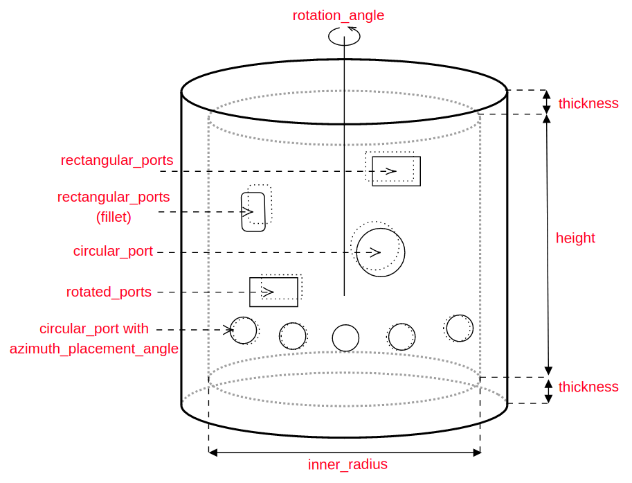
CircularPort()

- class CircularPort(inner_radius=30, distance=20, wall_thickness=2, flange_overhang=10, flange_thickness=5, flange_gap=0, blank_flange_thickness=5, workplane='ZY', rotation_axis='Z', extrusion_start_offset=100, center_point=(0, 0), name='circular_port_cutter', color=(0.984, 0.603, 0.6), rotation_angle=360, **kwargs)
Bases:
ShapeCreates an extruded pipe with a flange end and optional.
- Parameters:
inner_radius – inner_radius (cm) of tubular section.
distance – extruded distance (cm) of the tubular section.
wall_thickness – the radial thickness of the tubular section wall.
flange_overhang – the distance of the flange overhang or lip.
flange_thickness – the thickness of the flange, should be a positive number. Set to None if no blank flange is required.
blank_flange_thickness – the thickness of the blank flange
center_point – center point of the port cutter. Defaults to (0, 0).
workplane – workplane in which the port cutters are created. Defaults to “ZY”.
rotation_axis – axis around which the port cutters are rotated and placed. Defaults to “Z”.
extrusion_start_offset – the distance between 0 and the start of the extrusion. Defaults to 1..
name – defaults to “circular_port_cutter”.
- create_solid()
Creates a extruded 3d solid using points with circular edges.
- Returns:
A 3D solid volume
- Return type:
A CadQuery solid
- find_points()
Calculates the shape points. Empty method which some components overright when inheritting.
PortCutterRotated()
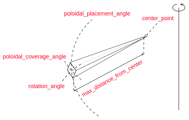
- class PortCutterRotated(center_point, polar_coverage_angle=10.0, polar_placement_angle=0.0, max_distance_from_center=3000.0, fillet_radius=0.0, rotation_angle=10.0, name='port_cutter', **kwargs)
Bases:
RotateStraightShapeCreates wedges from a central point with angular extent in polar direction. To control the width the rotation_angle argument can be used. This is useful as a cutting volume for the creation of ports in blankets.
- Parameters:
center_point (tuple of floats) – the center point where the ports are aimed towards, typically the center of the plasma.
polar_coverage_angle (float) – the angular extent of port in the polar direction (degrees). Defaults to 10.0.
polar_placement_angle (float) – The angle used when rotating the shape on the polar axis. 0 degrees is the outboard equatorial point. Defaults to 0.0.
max_distance_from_center (float) – the maximum distance from the center point outwards (cm). Default 3000.0.
fillet_radius (float, optional) – If not None, radius (cm) of fillets added to all edges. Defaults to 0.0.
rotation_angle (float, optional) – defaults to 10.0.
name (str, optional) – defaults to “port_cutter”.
- add_fillet()
adds fillets to all edges
- find_points()
Finds the XZ points joined by straight connections that describe the 2D profile of the port cutter.
PortCutterRectangular()
- class PortCutterRectangular(height, width, distance, center_point=(0, 0), workplane='ZY', rotation_axis='Z', extrusion_start_offset=1.0, fillet_radius=None, name='rectangular_port_cutter', **kwargs)
Bases:
ExtrudeStraightShapeCreates an extruded shape with a rectangular section that is used to cut other components (eg. blanket, vessel,..) in order to create ports.
- Parameters:
height – height (cm) of the port cutter.
width – width (cm) of the port cutter.
distance – extruded distance (cm) of the port cutter.
center_point – Center point of the port cutter. Defaults to (0, 0).
workplane – workplane in which the port cutters are created. Defaults to “ZY”.
rotation_axis – axis around which the port cutters are rotated and placed. Defaults to “Z”.
extrusion_start_offset (float, optional) – the distance between 0 and the start of the extrusion. Defaults to 1..
fillet_radius (float, optional) – If not None, radius (cm) of fillets added to edges orthogonal to the Z direction. Defaults to None.
name (str, optional) – defaults to “rectangular_port_cutter”.
- find_points()
Calculates the shape points. Empty method which some components overright when inheritting.
PortCutterCircular()
- class PortCutterCircular(radius, distance, center_point=(0, 0), workplane='ZY', rotation_axis='Z', extrusion_start_offset=1.0, name='circular_port_cutter', **kwargs)
Bases:
ExtrudeCircleShapeCreates an extruded shape with a circular section that is used to cut other components (eg. blanket, vessel,..) in order to create ports.
- Parameters:
radius – radius (cm) of port cutter.
distance – extruded distance (cm) of the port cutter.
center_point – center point of the port cutter. Defaults to (0, 0).
workplane – workplane in which the port cutters are created. Defaults to “ZY”.
rotation_axis – axis around which the port cutters are rotated and placed. Defaults to “Z”.
extrusion_start_offset – the distance between 0 and the start of the extrusion. Defaults to 1..
name – defaults to “circular_port_cutter”.
- find_points()
Calculates the shape points. Empty method which some components overright when inheritting.
Plasmas
Plasma()
- class Plasma(elongation=2.0, major_radius=450.0, minor_radius=150.0, triangularity=0.55, vertical_displacement=0.0, num_points=50, configuration='non-null', x_point_shift=0.1, name='plasma', **kwargs)
Bases:
RotateSplineShapeCreates a double null tokamak plasma shape that is controlled by 4 shaping parameters.
- Parameters:
elongation – the elongation of the plasma.
major_radius – the major radius of the plasma (cm).
minor_radius – the minor radius of the plasma (cm).
triangularity – the triangularity of the plasma.
vertical_displacement – the vertical_displacement of the plasma (cm)..
num_points – number of points to describe the shape.
configuration – plasma configuration (“non-null”, “single-null”, “double-null”).
x_point_shift – shift parameters for locating the X points in [0, 1]..
name –
- compute_x_points()
Computes the location of X points based on plasma parameters and configuration
- Returns:
lower and upper x points coordinates. None if no x points
- Return type:
((float, float), (float, float))
- find_points()
Finds the XZ points that describe the 2D profile of the plasma.
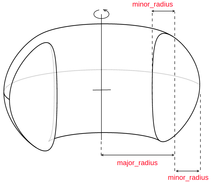
PlasmaFromPoints()
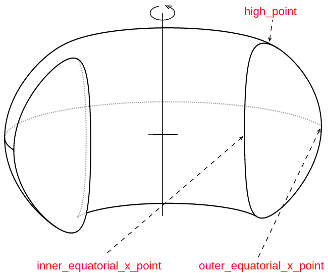
- class PlasmaFromPoints(outer_equatorial_x_point, inner_equatorial_x_point, high_point, **kwargs)
Bases:
PlasmaCreates a double null tokamak plasma shape that is controlled by 3 coordinates.
- Parameters:
outer_equatorial_x_point – the x value of the outer equatorial of the plasma (cm).
inner_equatorial_x_point – the x value of the inner equatorial of the plasma (cm).
high_point (tuple of 2 floats) – the (x,z) coordinate values of the top of the plasma (cm).
PlasmaBoundaries()

- class PlasmaBoundaries(A=0.05, elongation=2.0, major_radius=450.0, minor_radius=150.0, triangularity=0.55, vertical_displacement=0.0, configuration='non-null', x_point_shift=0.1, **kwargs)
Bases:
PlasmaCreates a double null tokamak plasma shape that is controlled by 5 shaping parameters using the plasmaboundaries package to calculate points. For more details see: http://github.com/fusion-energy/plasmaboundaries
- Parameters:
A – plasma parameter see plasmaboundaries doc.
elongation – the elongation of the plasma.
major_radius – the major radius of the plasma (cm).
minor_radius – the minor radius of the plasma (cm).
triangularity – the triangularity of the plasma.
vertical_displacement – the vertical_displacement of the plasma (cm).
configuration (str, optional) – plasma configuration (“non-null”, “single-null”, “double-null”).
x_point_shift – Shift parameters for locating the X points in [0, 1]. Defaults to 0.1.
- find_points()
Finds the XZ points that describe the 2D profile of the plasma.
Toroidal Field Coils
TFCoilCasing()


- class TFCoilCasing(magnet, inner_offset, outer_offset, vertical_section_offset, **kwargs)
Bases:
ExtrudeMixedShapeCasing component for TF coils
- Parameters:
magnet – TF coil shape
inner_offset – radial distance between inner coil surface and inner casing surface (cm)
outer_offset – radial distance between outer coil surface and outer casing surface (cm)
vertical_section_offset – radial distance between outer coil surface and outer vertical section surface (cm)
distance – extrusion distance (cm)
- create_solid()
Creates an extruded 3d solid using points connected with straight and spline edges.
- Returns:
A CadQuery solid: A 3D solid volume
- find_points()
Calculates the shape points. Empty method which some components overright when inheritting.
ToroidalFieldCoilRectangle()


- class ToroidalFieldCoilRectangle(name='toroidal_field_coil', horizontal_start_point=(20, 200), vertical_mid_point=(350, 0), thickness=30, distance=20, number_of_coils=12, with_inner_leg=True, azimuth_start_angle=0, vertical_displacement=0.0, rotation_angle=360.0, color=(0.0, 0.0, 1.0), **kwargs)
Bases:
ToroidalFieldCoilCreates a rectangular shaped toroidal field coil.
- Parameters:
horizontal_start_point – the (x,z) coordinates of the inner upper point (cm).
vertical_mid_point – the (x,z) coordinates of the mid point of the vertical section (cm).
thickness – the thickness of the toroidal field coil.
distance – the extrusion distance.
number_of_coils – the number of tf coils. This changes by the azimuth_placement_angle dividing up 360 degrees by the number of coils.
with_inner_leg – include the inner tf leg. Defaults to True.
azimuth_start_angle – The azimuth angle to for the first TF coil which offsets the placement of coils around the azimuthal angle
- find_points()
Finds the XZ points joined by straight connections that describe the 2D profile of the poloidal field coil shape.
ToroidalFieldCoilCoatHanger()
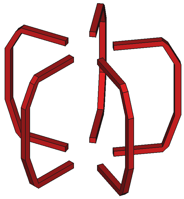
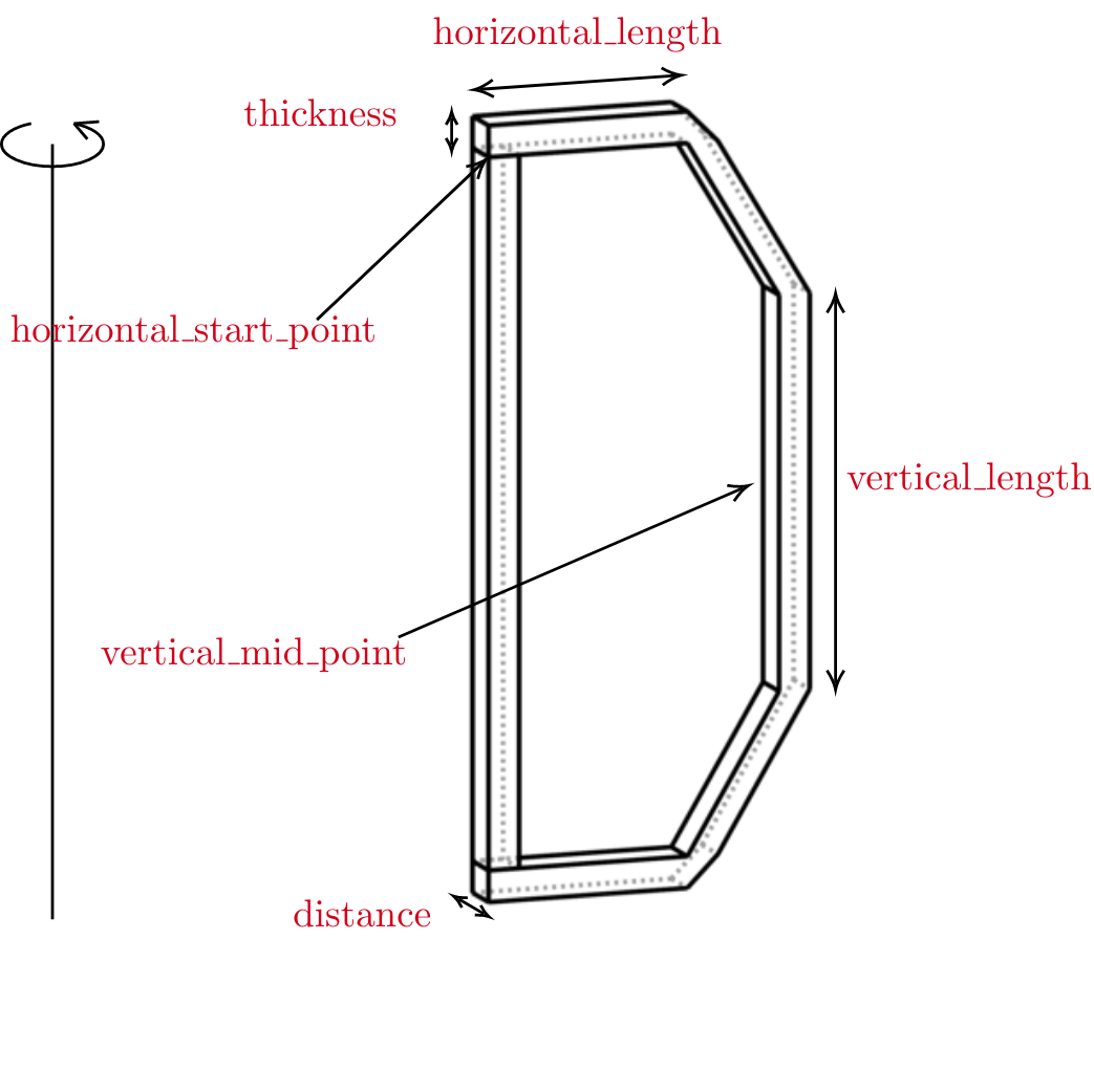

- class ToroidalFieldCoilCoatHanger(name='toroidal_field_coil', horizontal_start_point=(40, 200), horizontal_length=200, vertical_mid_point=(400, 0), vertical_length=250, thickness=30, distance=20, number_of_coils=12, with_inner_leg=True, azimuth_start_angle=0, vertical_displacement=0.0, rotation_angle=360.0, color=(0.0, 0.0, 1.0), **kwargs)
Bases:
ToroidalFieldCoilCreates a coat hanger shaped toroidal field coil.
- Parameters:
horizontal_start_point – the (x,z) coordinates of the inner upper point (cm).
horizontal_length – the radial length of the horizontal section of the TF coil (cm).
vertical_mid_point – the (x,z) coordinates of the mid point of the outboard vertical section (cm).
vertical_length – the radial length of the outboard vertical section of the TF coil (cm).
thickness – the thickness of the toroidal field coil.
distance – the extrusion distance.
number_of_coils – the number of TF coils. This changes with azimuth_placement_angle dividing up 360 degrees by the number of coils.
with_inner_leg – Include the inner TF leg. Defaults to True.
azimuth_start_angle – The azimuth angle to for the first TF coil which offsets the placement of coils around the azimuthal angle
- find_points()
Finds the XZ points joined by straight connections that describe the 2D profile of the poloidal field coil shape.
ToroidalFieldCoilPrincetonD()
- class ToroidalFieldCoilPrincetonD(name='toroidal_field_coil', R1=100, R2=300, thickness=30, distance=20, number_of_coils=12, vertical_displacement=0.0, with_inner_leg=True, azimuth_start_angle=0, rotation_angle=360.0, color=(0.0, 0.0, 1.0), **kwargs)
Bases:
ToroidalFieldCoilToroidal field coil based on Princeton-D curve
- Parameters:
R1 – smallest radius (cm)
R2 – largest radius (cm)
thickness – magnet thickness (cm)
distance – extrusion distance (cm)
number_of_coils – the number of tf coils. This changes by the azimuth_placement_angle dividing up 360 degrees by the number of coils.
vertical_displacement – vertical displacement (cm). Defaults to 0.0.
with_inner_leg – Include the inner tf leg. Defaults to True.
azimuth_start_angle – The azimuth angle to for the first TF coil which offsets the placement of coils around the azimuthal angle
rotation_angle – rotation angle of solid created. A cut is performed from rotation_angle to 360 degrees. Defaults to 360.0.
- find_points()
Finds the XZ points joined by connections that describe the 2D profile of the toroidal field coil shape.
ToroidalFieldCoilTripleArc()
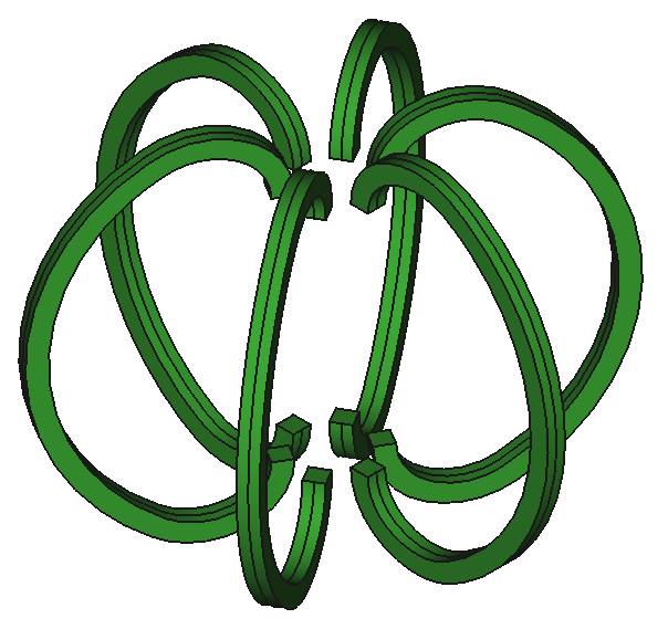

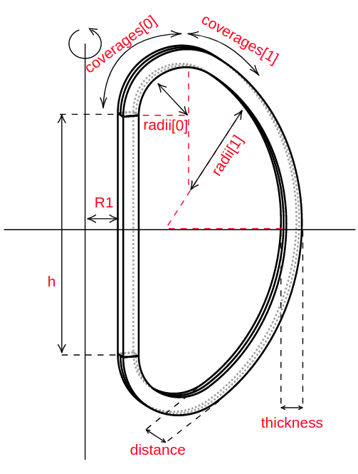
- class ToroidalFieldCoilTripleArc(name='toroidal_field_coil', R1=80, h=200, radii=(70, 100), coverages=(60, 60), thickness=30, distance=20, number_of_coils=12, vertical_displacement=0.0, with_inner_leg=True, azimuth_start_angle=0, rotation_angle=360.0, color=(0.0, 0.0, 1.0), **kwargs)
Bases:
ToroidalFieldCoilToroidal field coil made of three arcs
- Parameters:
R1 – smallest radius (cm).
h – height of the straight section (cm).
radii – radii of the small and medium arcs (cm).
coverages – coverages of the small and medium arcs (deg).
thickness – magnet thickness (cm).
distance – extrusion distance (cm).
number_of_coils – the number of TF coils. This changes by the azimuth_placement_angle dividing up 360 degrees by the number of coils.
vertical_displacement – vertical displacement (cm). Defaults to 0.0.
with_inner_leg – Include the inner tf leg. Defaults to True.
azimuth_start_angle – The azimuth angle to for the first TF coil which offsets the placement of coils around the azimuthal angle
- find_points()
Finds the XZ points joined by connections that describe the 2D profile of the toroidal field coil shape.
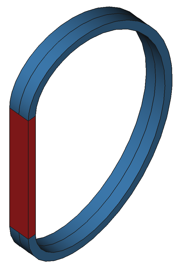
ToroidalFieldCoilRectangleRoundCorners()
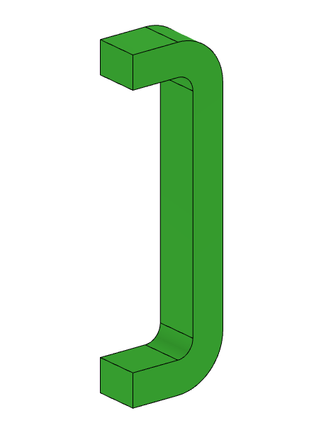
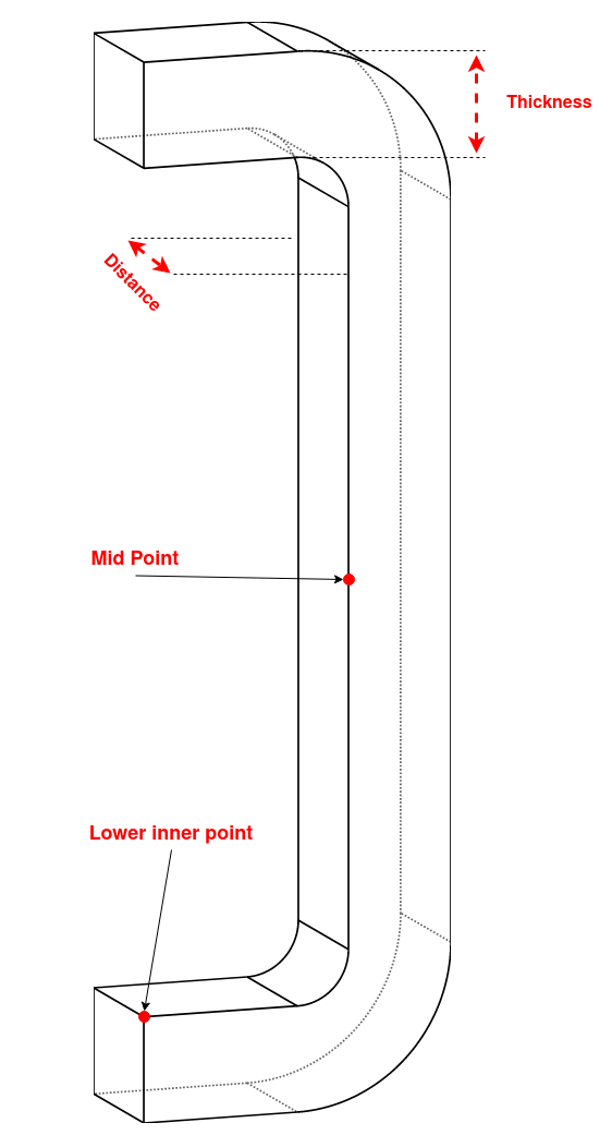
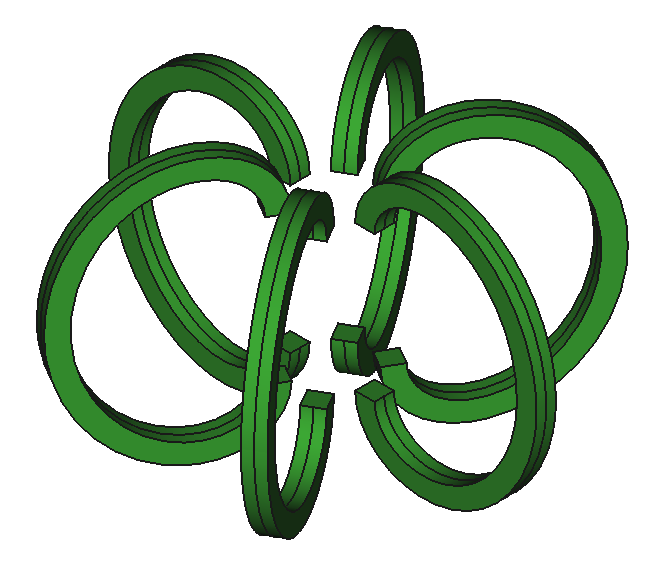
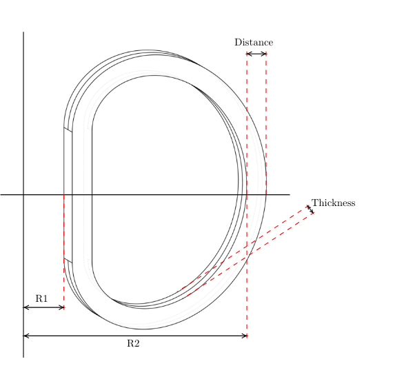
- class ToroidalFieldCoilRectangleRoundCorners(name='toroidal_field_coil', lower_inner_coordinates=(100, 250), mid_point_coordinates=(500, 0), thickness=30, distance=20, number_of_coils=12, with_inner_leg=True, azimuth_start_angle=0, color=(0.0, 0.0, 1.0), **kwargs)
Bases:
ExtrudeMixedShapeCreates geometry for TF coil with rounded corners. Finds the coordinates for vertices of a TF coil, in a 2D profile on the XZ plane using the main function find_points() which takes 3 positional arguments for the TF coil parameters, and takes three additional boolean arguments.
- Parameters:
lower_inner_coordinates – the (X,Z) coordinate of the inner corner of the lower end of the coil (cm)
mid_point_coordinates – the (X,Z) coordinate of the mid point of the vertical section (cm)
thickness – The thickness in the (X,Z) plane of the toroidal field coils (cm)
extrusiondistance – The total extruded thickness of the coils when in the y-direction (centered extrusion)
coil_count – The number of coils placed in the model (changing azimuth_placement_angle by dividing 360 by the amount given). Defaults to 1
with_inner_leg – Boolean to include the inside of the Coils
azimuth_start_angle – The azimuth angle to for the first TF coil which offsets the placement of coils around the azimuthal angle
- create_solid()
Creates a Cadquery 3D geometry
- Returns:
A 3D solid Volume
- Return type:
CadQuery solid
- find_azimuth_placement_angle()
Finds the placement angles from the number of coils given in a 360 degree
- find_points()
lower_inner_coordinates must be a 2 element tuple mid_point_coordinates must be a 2 elemenet tuple thickness must be a float or an int
Vacuum Vessels
VacuumVessel()


- class VacuumVessel(height, inner_radius, thickness, **kwargs)
Bases:
RotateStraightShapeA cylindrical vessel volume with constant thickness.
- Parameters:
height – height of the vessel.
inner_radius – the inner radius of the vessel.
thickness – thickness of the vessel
- find_points()
Finds the XZ points joined by straight connections that describe the 2D profile of the vessel shape.
VacuumVesselInnerLeg()


- class VacuumVesselInnerLeg(inner_height, inner_radius, inner_leg_radius, thickness, **kwargs)
Bases:
RotateStraightShapeA cylindrical vessel volume with constant thickness.
- Parameters:
inner_height – height of the vessel.
inner_radius – the inner radius of the vessel.
inner_leg_radius – the inner radius of the inner leg.
thickness – thickness of the vessel
- create_solid()
Creates a 3d solid using points with straight edges. Individual solids in the compound can be accessed using .Solids()[i] where i is an int
- Returns:
A CadQuery solid: A 3D solid volume
- find_points()
Finds the XZ points joined by straight connections that describe the 2D profile of the vessel shape.
CapsuleVacuumVessel()

- class CapsuleVacuumVessel(radius, outer_start_point, thickness, **kwargs)
Bases:
RotateMixedShapeA cylindrical vessel volume with constant thickness that has addition hemispherical head.
- Parameters:
outer_start_point – the x,z coordinates of the outer bottom of the vacuum vessel
radius – the radius from which the centres of the vessel meets the outer circumference.
thickness – the radial thickness of the vessel in cm.
- find_points()
Finds the XZ points joined by straight and circle connections that describe the 2D profile of the vessel shape.
DishedVacuumVessel()

- class DishedVacuumVessel(radius=300, center_point=0, dish_height=50, cylinder_height=400, thickness=15, name='dished_vessel', **kwargs)
Bases:
RotateMixedShapeA cylindrical vessel volume with constant thickness with a simple dished head. This style of tank head has no knuckle radius or straight flange.
- Parameters:
radius – the radius from which the centres of the vessel meets the outer circumference.
center_point – the x,z coordinates of the center of the vessel
dish_height – the height of the dish section. This is also the chord heigh of the circle used to make the dish.
cylinder_height – the height of the cylindrical section of the vacuum vessel.
thickness – the radial thickness of the vessel in cm.
- create_solid()
Creates a rotated 3d solid using points with circular edges.
- Returns:
A 3D solid volume
- Return type:
A CadQuery solid
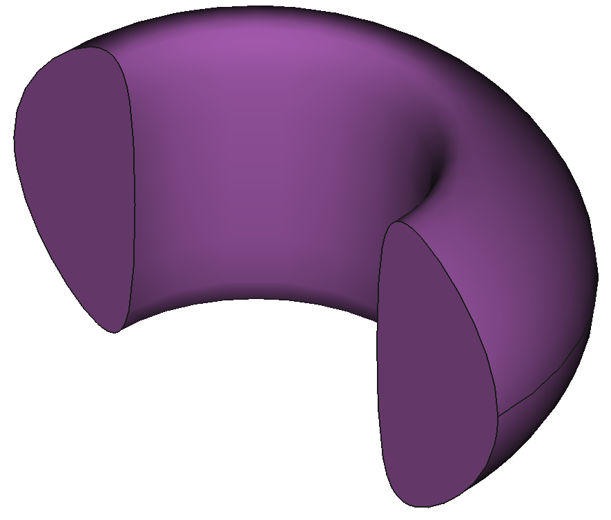
ConstantThicknessDome()
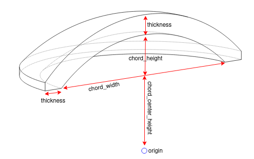
- class ConstantThicknessDome(thickness=10, chord_center_height=0, chord_width=100, chord_height=20, upper_or_lower='upper', name='constant_thickness_dome', **kwargs)
Bases:
RotateMixedShapeA cylindrical vessel volume with constant thickness with a simple dished head. This style of tank head has no knuckle radius or straight flange. The dished shape is made from a chord of a circle.
- Parameters:
thickness – the radial thickness of the dome.
chord_center_height – the vertical position of the chord center
chord_width – the width of the chord base
chord_height – the height of the chord which is also distance between the chord_center_height and the inner surface of the dome
upper_or_lower – Curves the dish with a positive or negative direction to allow the upper section or lower section of vacuum vessel domes to be made.
name – the name of the shape, used in the graph legend and as a filename prefix when exporting.
- create_solid()
Creates a rotated 3d solid using points with circular edges.
- Returns:
A 3D solid volume
- Return type:
A CadQuery solid
- find_points()
Finds the XZ points joined by straight and circle connections that describe the 2D profile of the vessel shape.
Other components
ExtrudeRectangle()
- class ExtrudeRectangle(height, width, center_point, name='extrude_rectangle', **kwargs)
Bases:
ExtrudeStraightShapeCreates a rectangular extrusion.
- Parameters:
height – the vertical (z axis) height of the rectangle (cm).
width – the horizontal (x axis) width of the rectangle (cm).
center_point – the center of the rectangle (x,z) values (cm).
name – defaults to “extrude_rectangle”.
- find_points()
Finds the XZ points joined by straight connections that describe the 2D profile of the shape.
ExtrudeHollowRectangle()

- class ExtrudeHollowRectangle(height, width, distance, casing_thickness, name='extrude_hollow_rectangle', center_point=(0, 0), extrude_both=True, color=(0.5, 0.5, 0.5), azimuth_placement_angle=0.0, workplane='XZ', cut=None, intersect=None, union=None, extrusion_start_offset=0.0, **kwargs)
Bases:
ExtrudeStraightShapeCreates a rectangular with a hollow section extrusion.
- Parameters:
height – the height of the internal hollow section.
width – the width of the internal hollow section.
distance – the depth of the internal hollow section.
casing_thickness – the thickness of the casing around the hollow section.
name – defaults to “extrude_rectangle”.
center_point – the center of the rectangle (x,z) values (cm).
- create_solid()
Creates an extruded 3d solid using points connected with straight and spline edges.
- Returns:
A CadQuery solid: A 3D solid volume
- find_points()
Finds the XZ points joined by straight connections that describe the 2D profile of the shape.
HexagonPin()

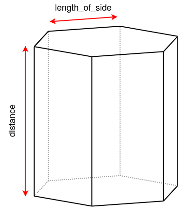
- class HexagonPin(length_of_side, distance, center_point=(0, 0), name='hexagon_pin', **kwargs)
Bases:
ExtrudeStraightShapeCreates an extruded hexagon by a provided distance about a center point.
- Parameters:
length_of_side – the length of one side of the hexagon (mm).
distance – extruded distance along the y-direction (mm).
center_point – the center of the hexagon on the x-z plane (mm).
name – defaults to “hexagon_pin”.
- find_points()
Finds the XZ points joined by straight connections that describe the 2D profile of the hexagon faced shape.
RotatedTrapezoid()

- class RotatedTrapezoid(length_1, length_2, length_3, pivot_point, pivot_angle=0.0, name='rotated_trapezoid', **kwargs)
Bases:
RotateStraightShapeCreates a rotated trapezoid (truncated triangle) shape.
- Parameters:
length_1 – the length of the top parallel edge of the trapezoid (cm).
length_2 – the length of the base parallel edge of the trapezoid (cm).
length_3 – the height of the trapezoid, the distances from top to base (cm).
pivot_point – the coordinates of the center of rotation (x,z). The pivot point is located in the center of the length_1 edge (cm).
pivot_angle – the angle (in degrees) to pivot (rotate) the shape by around the pivot point. Defaults to 0.
name – defaults to “rotated_trapezoid”.
- find_points()
Finds the XZ points joined by straight connections that describe the 2D profile of the trapezoid shape.
RotatedIsoscelesTriangle
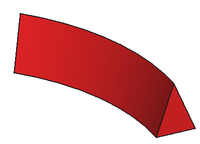
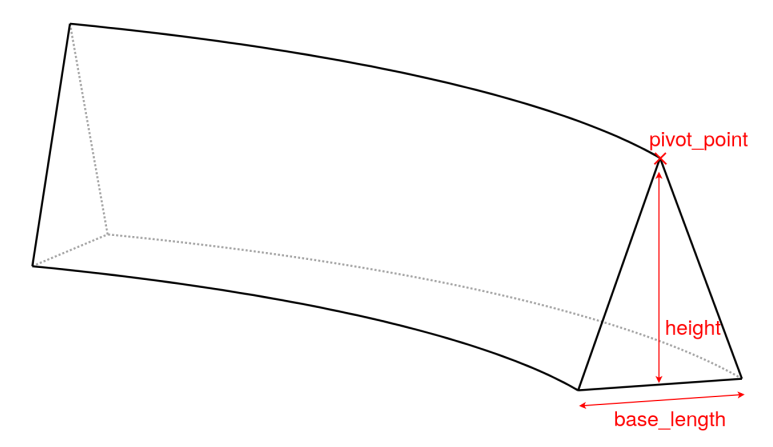
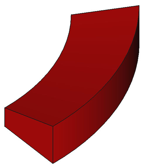
- class RotatedIsoscelesTriangle(base_length, height, pivot_point, pivot_angle=0.0, name='rotated_triangle', **kwargs)
Bases:
RotateStraightShapeCreates a rotated triangle (truncated triangle) shape.
- Parameters:
base_length – the length of the base of the triangle (cm).
height – the height of the triangle (cm).
pivot_point – the coordinates of the tip of the triangle at the opposite side to the base of the triangle.
pivot_angle – the angle (in degrees) to pivot (rotate) the shape by around the pivot point. Defaults to 0.
name – defaults to “rotated_triangle”.
- find_points()
Finds the XZ points joined by straight connections that describe the 2D profile of the triangle shape.
Parametric Reactors
These some of the reactor designs that can be created using the Paramak.

Inertial Confinement
FlfSystemCodeReactor()


- class FlfSystemCodeReactor(inner_blanket_radius=100.0, blanket_thickness=70.0, blanket_height=500.0, lower_blanket_thickness=50.0, upper_blanket_thickness=40.0, blanket_vv_gap=20.0, upper_vv_thickness=10.0, vv_thickness=10.0, lower_vv_thickness=10.0, rotation_angle=180.0)
Bases:
ReactorCreates the 3D geometry for the a simplified FLF reactor model based on parameters. Model design was originally presented at University of York in 2019. Model shown at 50 mins 48 seconds in presentation https://www.youtube.com/watch?v=DtvcEkIb4D4
- Parameters:
inner_blanket_radius – The radial distance between the center of the reactor on the start of the blanket (cm).
blanket_thickness – The radial thickness of the blanket (cm).
blanket_height – The height (z axis direction) of the blanket (cm).
lower_blanket_thickness – The thickness (z axis direction) of the lower blanket pool (cm).
upper_blanket_thickness – The thickness (z axis direction) of the upper blanket pool (cm).
blanket_vv_gap – The radial distance between the outer edge of the blanket and the inner edge of the vaccum vessel (cm).
upper_vv_thickness – The thickness (z axis direction) of the upper section of vaccum vessel (cm).
vv_thickness – The radial thickness of the vaccum vessel (cm)
lower_vv_thickness – The thickness (z axis direction) of the lower section of vaccum vessel (cm).
rotation_angle – The angle of the sector simulated. Set to 360 for simulations and less when creating models for visualization.
- create_solids()
Creates a list of paramak.Shape for components and saves it in self.shapes_and_components
BallReactors
BallReactor()

The above image is colored by components. The TF coils are blue, the PF coils are red, PF coil cases are yellow, the center column shielding is dark green, the blanket is light green, the divertor is orange, the firstwall is grey and the rear wall of the blanket is teal.

- class BallReactor(inner_bore_radial_thickness=10.0, inboard_tf_leg_radial_thickness=30.0, center_column_shield_radial_thickness=60.0, divertor_radial_thickness=150.0, inner_plasma_gap_radial_thickness=30.0, plasma_radial_thickness=300.0, outer_plasma_gap_radial_thickness=30.0, firstwall_radial_thickness=30.0, blanket_radial_thickness=50.0, blanket_rear_wall_radial_thickness=30.0, elongation=2.0, triangularity=0.55, plasma_gap_vertical_thickness=50.0, divertor_to_tf_gap_vertical_thickness=0.0, number_of_tf_coils=12, rear_blanket_to_tf_gap=None, pf_coil_radial_thicknesses=[], pf_coil_vertical_thicknesses=[], pf_coil_radial_position=[], pf_coil_vertical_position=[], pf_coil_case_thicknesses=[], outboard_tf_coil_radial_thickness=None, outboard_tf_coil_poloidal_thickness=None, divertor_position='both', rotation_angle=180.0)
Bases:
ReactorCreates geometry for a simple ball reactor including a plasma, cylindrical center column shielding, square toroidal field coils. There is no inboard breeder blanket on this ball reactor like most spherical reactors.
- Parameters:
inner_bore_radial_thickness – the radial thickness of the inner bore (cm)
inboard_tf_leg_radial_thickness – the radial thickness of the inner leg of the toroidal field coils (cm)
center_column_shield_radial_thickness – the radial thickness of the center column shield (cm)
divertor_radial_thickness – the radial thickness of the divertor (cm), this fills the gap between the center column shield and blanket
inner_plasma_gap_radial_thickness – the radial thickness of the inboard gap between the plasma and the center column shield (cm)
plasma_radial_thickness – the radial thickness of the plasma
outer_plasma_gap_radial_thickness – the radial thickness of the outboard gap between the plasma and firstwall (cm)
firstwall_radial_thickness – the radial thickness of the first wall (cm)
blanket_radial_thickness – the radial thickness of the blanket (cm)
blanket_rear_wall_radial_thickness – the radial thickness of the rear wall of the blanket (cm)
elongation – the elongation of the plasma
triangularity – the triangularity of the plasma
plasma_gap_vertical_thickness – the vertical thickness of the gap between the plasma and firstwall (cm).
divertor_to_tf_gap_vertical_thickness – the vertical thickness of the gap between the divertor and the TF coils.
number_of_tf_coils – the number of tf coils
rear_blanket_to_tf_gap – the radial distance between the back of the blankets and the start of the TF coils.
pf_coil_radial_thicknesses – the radial thickness of each poloidal field coil.
pf_coil_vertical_thicknesses – the vertical thickness of each poloidal field coil.
pf_coil_radial_position – The radial (x) position(s) of the centers of the poloidal field coils.
pf_coil_vertical_position – The vertical (z) position(s) of the centers of the poloidal field coils.
pf_coil_case_thicknesses – the thickness(s) to use in both the radial and vertical direction for the casing around the pf coils. Each float value in the list will be applied to the pf coils one by one. To have no casing set each entry to 0 or leave as an empty list.
outboard_tf_coil_radial_thickness – the radial thickness of the toroidal field coil.
outboard_tf_coil_poloidal_thickness – the poloidal thickness of the toroidal field coil.
divertor_position – the position of the divertor, “upper”, “lower” or “both”.
rotation_angle – the angle of the sector that is desired.
- create_solids()
Creates a list of paramak.Shape for components and saves it in self.shapes_and_components
SegmentedBlanketBallReactor()

The above image is colored by components. The TF coils are blue, the PF coils are red, PF coil cases are yellow, the center column shielding is dark green, the blanket is light green, the divertor is orange, the firstwall is grey and the rear wall of the blanket is teal.
Note that there is an odd number of blanket segments in this diagram so that the blanket breeder zone and the first wall can be see in this 180 slice.

Note the above image has the plasma purposefully hidden on the right hand side so that the internal blanket structure can be seen.
- class SegmentedBlanketBallReactor(gap_between_blankets=15.0, number_of_blanket_segments=12, blanket_fillet_radius=10.0, **kwargs)
Bases:
BallReactorCreates geometry for a single ball reactor with a single divertor including a plasma, cylindrical center column shielding, square toroidal field coils. There is no inboard breeder blanket on this ball reactor like most spherical reactors.
- Parameters:
gap_between_blankets (float) – the distance between adjacent blanket segments,
number_of_blanket_segments (int) – the number of segments to divide the blanket up into. This for a full 360 degrees rotation
blanket_fillet_radius (float) – the fillet radius to apply to the interface between the firstwall and th breeder zone. Set to 0 for no fillet. Defaults to 10.0.
- property number_of_blanket_segments
Sets the SegmentedBlanketBallReactor.number_of_blanket_segments attribute which controls the number of blanket segments.
SingleNullBallReactor()

The above image is colored by components. The TF coils are blue, the PF coils are red, PF coil cases are yellow, the center column shielding is dark green, the blanket is light green, the divertor is orange, the firstwall is grey and the rear wall of the blanket is teal.
- class SingleNullBallReactor(divertor_position='upper', **kwargs)
Bases:
BallReactorCreates geometry for a single ball reactor with a single divertor including a plasma, cylindrical center column shielding, square toroidal field coils. There is no inboard breeder blanket on this ball reactor like most spherical reactors.
- Parameters:
divertor_position (str) – Defaults to “upper”.
Submersion Tokamaks
SubmersionTokamak()

The above image is colored by components, the TF coils are blue, the PF coils are red, PF coil cases are yellow, the center column shielding is dark green, the blanket is light green, the divertor is orange, the firstwall is grey and the rear wall of the blanket is teal and the support legs are black.

- class SubmersionTokamak(inner_bore_radial_thickness=30.0, inboard_tf_leg_radial_thickness=30, center_column_shield_radial_thickness=30, inboard_blanket_radial_thickness=80, firstwall_radial_thickness=20, inner_plasma_gap_radial_thickness=50, plasma_radial_thickness=200, divertor_radial_thickness=80, support_radial_thickness=90, outer_plasma_gap_radial_thickness=50, outboard_blanket_radial_thickness=30, blanket_rear_wall_radial_thickness=30, elongation=2.0, triangularity=0.5, number_of_tf_coils=16, rotation_angle=180.0, outboard_tf_coil_radial_thickness=None, rear_blanket_to_tf_gap=None, outboard_tf_coil_poloidal_thickness=None, pf_coil_radial_thicknesses=[], pf_coil_vertical_thicknesses=[], pf_coil_radial_position=[], pf_coil_vertical_position=[], pf_coil_case_thicknesses=[], divertor_position='both', support_position='both')
Bases:
ReactorCreates geometry for a simple submersion reactor including a plasma, cylindrical center column shielding, inboard and outboard breeder blanket, divertor (upper and lower), support legs. Optional coat hanger shaped toroidal field coils and pf coils.
- Parameters:
inner_bore_radial_thickness – the radial thickness of the inner bore (cm)
inboard_tf_leg_radial_thickness – the radial thickness of the inner leg of the toroidal field coils (cm)
center_column_shield_radial_thickness – the radial thickness of the center column shield (cm)
inboard_blanket_radial_thickness – the radial thickness of the inboard blanket (cm)
firstwall_radial_thickness – the radial thickness of the first wall (cm)
inner_plasma_gap_radial_thickness – the radial thickness of the inboard gap between the plasma and the center column shield (cm)
plasma_radial_thickness – the radial thickness of the plasma (cm)
divertor_radial_thickness – the radial thickness of the divertors (cm)
support_radial_thickness – the radial thickness of the upper and lower supports (cm)
outer_plasma_gap_radial_thickness – the radial thickness of the outboard gap between the plasma and the first wall (cm)
outboard_blanket_radial_thickness – the radial thickness of the blanket (cm)
blanket_rear_wall_radial_thickness – the radial thickness of the rear wall of the blanket (cm)
elongation – the elongation of the plasma
triangularity – the triangularity of the plasma
number_of_tf_coils – the number of tf coils.
rotation_angle – the angle of the sector that is desired.
outboard_tf_coil_radial_thickness – the radial thickness of the toroidal field coil.
rear_blanket_to_tf_gap – the radial distance between the rear of the blanket and the toroidal field coil.
outboard_tf_coil_poloidal_thickness – the vertical thickness of each poloidal field coil.
pf_coil_vertical_thicknesses – the vertical thickness of each poloidal field coil.
pf_coil_radial_thicknesses – the radial thickness of each poloidal field coil.
divertor_position – the position of the divertor, “upper”, “lower” or “both”. Defaults to “both”.
support_position – the position of the supports, “upper”, “lower” or “both”. Defaults to “both”.
- create_solids()
Creates a list of paramak.Shape for components and saves it in self.shapes_and_components
SingleNullSubmersionTokamak()

The above image is colored by component. The TF coils are blue, the PF coils are red, PF coil cases are yellow, the center column shielding is dark green, the blanket is light green, the divertor is orange, the firstwall is grey, the rear wall of the blanket is teal and the supports are black.
- class SingleNullSubmersionTokamak(divertor_position='upper', support_position='upper', **kwargs)
Bases:
SubmersionTokamakCreates geometry for a submersion reactor with a single divertor including a plasma, cylindrical center column shielding, square toroidal field coils. There is an inboard breeder blanket on this submersion reactor.
- Parameters:
divertor_position (str) – Defaults to “upper”.
support_position (str) – Defaults to “upper”.
Specific use case reactors
CenterColumnStudyReactor()

The above image is colored by component. The center column shielding is dark green, the blanket is light green, the divertor is orange, the firstwall is grey and the blanket is teal.
Note this reactor is purposefully simple so that center column parameter studies can be performed quickly.

- class CenterColumnStudyReactor(inner_bore_radial_thickness=20, inboard_tf_leg_radial_thickness=50.0, center_column_shield_radial_thickness_mid=50.0, center_column_shield_radial_thickness_upper=100.0, inboard_firstwall_radial_thickness=20.0, divertor_radial_thickness=100.0, inner_plasma_gap_radial_thickness=80.0, plasma_radial_thickness=200.0, outer_plasma_gap_radial_thickness=90, center_column_arc_vertical_thickness=520.0, elongation=2.3, triangularity=0.45, plasma_gap_vertical_thickness=40, rotation_angle=180.0)
Bases:
ReactorCreates geometry for a simple reactor that is optimised for carrying out parametric studies on the center column shield. Several aspects such as outboard magnets are intentionally missing from this reactor so that the model runs quickly and only includes components that have a significant impact on the center column shielding. This allows the neutronics simulations to run quickly and the column design space to be explored efficiently.
- Parameters:
inner_bore_radial_thickness (float) – the radial thickness of the inner bore (cm)
inboard_tf_leg_radial_thickness (float) – the radial thickness of the inner leg of the toroidal field coils (cm)
center_column_shield_radial_thickness_mid (float) – the radial thickness of the center column shield at the mid point (cm)
center_column_shield_radial_thickness_upper (float) – the radial thickness of the center column shield at the upper point (cm)
inboard_firstwall_radial_thickness (float) – the radial thickness of the inboard firstwall (cm)
divertor_radial_thickness (float) – the radial thickness of the divertor (cm)
inner_plasma_gap_radial_thickness (float) – the radial thickness of the inboard gap between the plasma and the center column shield (cm)
plasma_radial_thickness (float) – the radial thickness of the plasma (cm)
outer_plasma_gap_radial_thickness (float) – the radial thickness of the outboard gap between the plasma and the first wall (cm)
elongation (float) – the elongation of the plasma
triangularity (float) – the triangularity of the plasma
center_column_arc_vertical_thickness (float) – height of the outer hyperbolic profile of the center column shield.
plasma_gap_vertical_thickness (float) – the vertical thickness of the upper gap between the plasma and the blanket (cm)
rotation_angle (float) – the angle of the sector that is desired. Defaults to 360.0.
- create_solids()
Creates a 3d solids for each component.
- Returns:
A list of 3D solid volumes
- Return type:
A list of CadQuery solids
NegativeTriangularityReactor()


The above image is coloured by component. On the left the low_aspect attribute is True, whereas on the right, the low_aspect attribute is set to False, as well as the PF coils outside were moved +200 units from default outward.

- class NegativeTriangularityReactor(inner_tf_coil_thickness=100, vacuum_vessel_thickness=50, central_shield_thickness=30, wall_to_plasma_gap=150, plasma_radial_thickness=650, elongation=2, triangularity=0.6, inner_wall_thickness=20, blanket_thickness=105, rear_wall_thickness=20, divertor_radial_thickness=430, divertor_height_full=300, number_of_coils=12, tf_width=75, pf_coil_heights=[75, 75, 150, 75, 75], pf_coil_widths=[70, 70, 150, 70, 70], pf_coil_center_points=[(350, 850), (1350, 650), (1350, 0), (1350, -650), (350, -850)], pf_coil_casing_thickness=[15, 15, 15, 15, 15], rotation_angle=180, inner_bore_radius=50, port_side_lengths=[200, 200, 150], port_heights=[200, 100, 400], port_angles=[75, 170, 15], port_z_pos=[500, -500, 200], outer_tf_coil_thickness=None, low_aspect=False)
Bases:
ReactorNew class of reactor that builds a negative triangularity tokamak model.
- Parameters:
inner_tf_coil_thickness – radial thickness of the Toroidal Field coil’s inner leg (cm),
vacuum_vessel_thickness – the radial and vertical thickness of the vacuum vessel (cm),
central_shield_thickness – radial thickness of the central heat shield (cm),
wall_to_plasma_gap – gap of inner blanket wall and the plasma outter edge (cm),
plasma_radial_thickness – radial thickness of the plasma (2x minor radius) (cm),
elongation – plasma elongation,
triangularity – plasma triangularity - both positive or negative values will result in negative triangularity,
inner_wall_thickness – plasma facing blanket wall thickness (cm),
blanket_thickness – breeder blanket thickness (cm),
rear_wall_thickness – outer blanket wall thickness (cm),
divertor_radial_thickness – radial thickness of the divertor (cm),
divertor_height_full – divertor vertical thickness (cm),
number_of_coils – number of Toroidal Field coils around the reactor evenly spaced,
tf_width – Toroidal Field coil extrusion distance / thickness (cm),
pf_coil_heights – List of Poloidal field coil heights (cm),
pf_coil_widths – List of Poloidal field coil widths (cm),
pf_coil_center_points – List of Poloidal field coil center points on the XZ workplane (cm),
pf_coil_casing_thickness – List of Poloidal field coil casing thickness (cm),
rotation_angle – Angle of rotation arounbd the Z axis of which the reactor is shown - 180° shows half a reactor,
inner_bore_radius – Inner bore radial thickness (cm); Defaults to 5 cm,
port_side_lengths – List containing the side lengths of the ports (cm),
port_heights – List containing the heights of the ports (cm),
port_angles – List containing the angles of the ports center points (°),
port_z_pos – List containing the Z position of the ports as Zero in the centre of the reactor (cm),
outer_tf_coil_thickness – Outer Toroidal Field coil thickness (cm) - defaults to the inner Toroidal Field coil thickness,,
low_aspect – Boolean allowing a swift switch between a lower aspect-ratio reactor (True) where the inner blanket is cut by the center column, whereas (False) non-low-aspect will produce a full inner blanket and only part being cut by the centre column is the rear blanket wall,
Reactors from publications
EuDemoFrom2015PaperDiagram()

The above image is colored by component.
- class EuDemoFrom2015PaperDiagram(rotation_angle=180.0, number_of_tf_coils=16)
Bases:
ReactorCreates geometry of a simplified EU DEMO model based on the published diagram in Figure 2 of Definition of the basic DEMO tokamak geometry based on systems code studies. Published in Fusion Engineering and Design http://dx.doi.org/10.1016/j.fusengdes.2015.06.097 . Coordinates extracted from the figure are not exact and therefore this model does not perfectly represent the reactor.
- Parameters:
rotation_angle – the angle of the sector that is desired.
number_of_tf_coils – the number of tf coils to include in the model
- create_pf_coils()
Creates a 3d solids for each pf coil.
- Returns:
A list of 3D solid volumes
- Return type:
A list of CadQuery solids
- Return type:
list
- create_plasma()
Creates a 3d solids for the plasma.
- Returns:
A list of 3D solid volumes
- Return type:
A list of CadQuery solids
- Return type:
list
- create_solids()
Creates a 3d solids for each component.
- Returns:
A list of 3D solid volumes
- Return type:
A list of CadQuery solids
- create_tf_coils(vac_vessel_inner, vac_vessel)
Creates a 3d solids for each tf coil.
- Parameters:
vac_vessel (Paramak.Shape) – The vac_vessel that is used in a Boolean cut opperation to prevent overlaps
vac_vessel_inner (Paramak.Shape) – The vac_vessel_inner that is used in a Boolean cut opperation to prevent overlaps
- Returns:
A list of 3D solid volumes
- Return type:
A list of CadQuery solids
- Return type:
list
- create_vessel_components()
Creates a 3d solids for each vessel component.
- Returns:
A list of 3D solid volumes
- Return type:
A list of CadQuery solids
- Return type:
list
IterFrom2020PaperDiagram()

The above image is colored by component.
- class IterFrom2020PaperDiagram(rotation_angle=180.0, number_of_tf_coils=18)
Bases:
ReactorCreates geometry of a simplified ITER model. The geometry was based on “ITER Project: International Cooperation and Energy Investment” available at https://link.springer.com/chapter/10.1007/978-3-030-42913-3_26 Many shapes are built-in paramak shapes therefore the model does not match the diagram exactly.
- Parameters:
rotation_angle – the angle of the sector that is desired.
number_of_tf_coils – the number of tf coils to include in the model
- create_pf_coils()
Creates a 3d solids for each pf coil.
- Returns:
A list of 3D solid volumes
- Return type:
A list of CadQuery solids
- Return type:
list
- create_plasma()
Creates a 3d solids for the plasma.
- Returns:
A list of 3D solid volumes
- Return type:
A list of CadQuery solids
- Return type:
list
- create_solids()
Creates a 3d solids for each component.
- Returns:
A list of 3D solid volumes
- Return type:
A list of CadQuery solids
- create_tf_coils()
Creates a 3d solids for each tf coil.
Args:
- Returns:
A list of 3D solid volumes
- Return type:
A list of CadQuery solids
- Return type:
list
- create_vessel_components()
Creates a 3d solids for each vessel component.
- Returns:
A list of 3D solid volumes
- Return type:
A list of CadQuery solids
- Return type:
list
SparcFrom2020PaperDiagram()

- class SparcFrom2020PaperDiagram(rotation_angle=180.0)
Bases:
ReactorCreates geometry of a simple SPARC reactor based on the published diagram in Figure 4 of Overview of the SPARC tokamak. Journal of Plasma Physics, 86(5), 865860502. doi:10.1017/S0022377820001257. Coordinates extracted from the figure are not exact and therefore this model does not perfectly represent the reactor.
- Parameters:
rotation_angle (float) – the angle of the sector that is desired. Defaults to 360.0.
- create_pf_coils()
Creates a 3d solids for each pf coil.
- Returns:
A list of 3D solid volumes
- Return type:
A list of CadQuery solids
- create_plasma()
Creates a 3d solids for the plasma.
- Returns:
A list of 3D solid volumes
- Return type:
A list of CadQuery solids
- create_solids()
Creates a 3d solids for each component.
- Returns:
A list of 3D solid volumes
- Return type:
A list of CadQuery solids
- create_tf_coils()
Creates a 3d solids for each tf coil.
- Returns:
A list of 3D solid volumes
- Return type:
A list of CadQuery solids
- create_vessel_components(vs_coils)
Creates a 3d solids for each vessel component.
- Parameters:
vs_coils (Paramak.Shape) – The vs coils that are used in a Boolean cut with the inner vessel.
- Returns:
A list of 3D solid volumes
- Return type:
A list of CadQuery solids
Shape() class
The Shape class is the container class for all Shapes and Components.
- class Shape(points=None, connection_type='mixed', name=None, color=(0.5, 0.5, 0.5), azimuth_placement_angle=0.0, workplane='XZ', rotation_axis=None, cut=None, intersect=None, union=None)
Bases:
objectA shape object that represents a 3d volume and can have materials and neutronics tallies assigned. Shape objects are not intended to be used directly by the user but provide basic functionality for user-facing classes that inherit from Shape. Provides a .show attribute for rendering in Jupyter Lab
- Parameters:
points (tuple of (float, float, float), optional) – the x, y, z coordinates of points that make up the shape. Defaults to None.
connection_type (str, optional) – The type of connection between points. Possible values are “straight”, “circle”, “spline”, “mixed”. Defaults to “mixed”.
name (str, optional) – the name of the shape, used in the graph legend by export_html. Defaults to None.
color ((float, float, float [, float]), optional) – The color to use when exporting as html graphs or png images. Can be in RGB or RGBA format with floats between 0 and 1. Defaults to (0.5, 0.5, 0.5).
azimuth_placement_angle (iterable of floats or float, optional) – the azimuth angle(s) used when positioning the shape. If a list of angles is provided, the shape is duplicated at all angles. Defaults to 0.0.
workplane – the orientation of the Cadquery workplane. Options include strings “XY”, “YZ”, “XZ” or a Cadquery.Plane(). Defaults to “XZ”.
rotation_axis (str or list, optional) – rotation axis around which the solid is rotated. If None, the rotation axis will depend on the workplane or path_workplane if applicable. Can be set to “X”, “-Y”, “Z”, etc. A custom axis can be set by setting a list of two XYZ floats. Defaults to None.
cut (paramak.shape or list, optional) – If set, the current solid will be cut with the provided solid or iterable in cut. Defaults to None.
intersect (paramak.shape or list, optional) – If set, the current solid will be interested with the provided solid or iterable of solids. Defaults to None.
union (paramak.shape or list, optional) – If set, the current solid will be united with the provided solid or iterable of solids. Defaults to None.
- property area
Get the total surface area of the Shape. Returns a float
- property areas
Get the surface areas of the Shape. Compound shapes provide a separate area value for each entry. Returns a list of floats
- property bounding_box
Calculates a bounding box for the Shape and returns the coordinates of the corners lower-left and upper-right. This function is useful when creating OpenMC mesh tallies as the bounding box is required in this form
- convert_all_circle_connections_to_splines(tolerance=0.1)
Replaces circle edges in Shape.processed_points points with spline edges. The spline control coordinates are obtained by faceting the circle edge with the provided tolerance. The Shape.processed_points will be updated to exclude the circle points and include the new spline points. This method works best when the connection before and after the circle is a straight connection type. This method is useful when converting the stp file into other formats due to errors in the conversion of circle edges.
- Parameters:
tolerance – the precision of the faceting.
- Returns:
The new points with spline connections
- Return type:
List[Tuple[float,float,str]]
- create_limits()
Finds the x,y,z limits (min and max) of the points that make up the face of the shape. Note the Shape may extend beyond this boundary if splines are used to connect points.
- Raises:
ValueError – if no points are defined
- Returns:
x_minimum, x_maximum, y_minimum, y_maximum, z_minimum, z_maximum
- Return type:
float, float, float, float, float, float
- Return type:
Tuple[float,float,float,float]
- export_2d_image(filename='shape.png', xmin=0.0, xmax=900.0, ymin=-600.0, ymax=600.0)
Exports a 2d image (png) of the reactor. Components are colored by their Shape.color property. If filename provided doesn’t end with .png then .png will be added.
- Parameters:
filename – the filename of the saved png image.
xmin – the minimum x value of the x axis. Defaults to 0..
xmax – the maximum x value of the x axis. Defaults to 900..
ymin – the minimum y value of the y axis. Defaults to -600..
ymax – the maximum y value of the y axis. Defaults to 600..
- Returns:
a plt object
- Return type:
matplotlib.plt()
- export_brep(filename='shape.brep')
Exports a brep file for the Shape.
- Parameters:
filename – the filename of exported the brep file.
- Returns:
filename of the brep created
- Return type:
str
- export_dagmc_h5m(filename='dagmc.h5m', min_mesh_size=5, max_mesh_size=20, verbose=False, volume_atol=1e-06, center_atol=1e-06, bounding_box_atol=1e-06, tags=None)
Export a DAGMC compatible h5m file for use in neutronics simulations. This method makes use of Gmsh to create a surface mesh of the geometry. MOAB is used to convert the meshed geometry into a h5m with parts tagged by using the reactor.shape_and_components.name properties. You will need Gmsh installed and MOAB installed to use this function. Acceptable tolerances may need increasing to match reactor parts with the parts in the intermediate Brep file produced during the process
- Parameters:
filename – the filename of the DAGMC h5m file to write
min_mesh_size – the minimum mesh element size to use in Gmsh. Passed into gmsh.option.setNumber(“Mesh.MeshSizeMin”, min_mesh_size)
max_mesh_size – the maximum mesh element size to use in Gmsh. Passed into gmsh.option.setNumber(“Mesh.MeshSizeMax”, max_mesh_size)
volume_atol – the absolute volume tolerance to allow when matching parts in the intermediate brep file with the cadquery parts
center_atol – the absolute center coordinates tolerance to allow when matching parts in the intermediate brep file with the cadquery parts
bounding_box_atol – the absolute volume tolerance to allow when matching parts in the intermediate brep file with the cadquery parts
tags – the dagmc tag to use in when naming the shape in the h5m file. If left as None then the Shape.name will be used. This allows the DAGMC geometry created to be compatible with a wider range of neutronics codes that have specific DAGMC tag requirements.
- Return type:
str
- export_html(filename='shape.html', facet_splines=True, facet_circles=True, tolerance=0.001, view_plane=None)
Creates a html graph representation of the points and connections for the Shape object. Shapes are colored by their .color property. Shapes are also labelled by their .name. If filename provided doesn’t end with .html then .html will be added.
- Parameters:
filename – the filename used to save the html graph. Defaults to shape.html
facet_splines – If True then spline edges will be faceted. Defaults to True.
facet_circles – If True then circle edges will be faceted. Defaults to True.
tolerance – faceting toleranceto use when faceting cirles and splines. Defaults to 1e-3.
view_plane – The plane to project. Options are ‘XZ’, ‘XY’, ‘YZ’, ‘YX’, ‘ZY’, ‘ZX’, ‘RZ’ and ‘XYZ’. Defaults to ‘RZ’. Defaults to the workplane of the paramak.Shape.
- Returns:
figure object
- Return type:
plotly.Figure()
- export_html_3d(filename='shape_3d.html', **kwargs)
Saves an interactive 3d html view of the Shape to a html file.
- Parameters:
filename – the filename used to save the html graph. Defaults to shape_3d.html
kwargs – keyword arguments passed to jupyter-cadquery show() function. See https://github.com/bernhard-42/jupyter-cadquery#usage for more details on acceptable keywords
- Returns:
filename of the created html file
- Return type:
str
- export_stl(filename, tolerance=0.001, angular_tolerance=0.1, verbose=True)
Exports an stl file for the Shape.solid.
- Parameters:
filename – the filename of exported the stl file. Defaults to None which will attempt to use the Shape.stl_filename. If both are None then a valueError will be raised.
tolerance – the deflection tolerance of the faceting
angular_tolerance – the angular tolerance, in radians
verbose – Enables (True) or disables (False) the printing of the file produced.
- Return type:
str
- export_stp(filename, units='mm', mode='solid', verbose=True)
Exports an stp file for the Shape.solid.
- Parameters:
filename – the filename of exported the stp file.
units – the units of the stp file, options are ‘cm’ or ‘mm’. Default is mm.
mode – the object to export can be either ‘solid’ which exports 3D solid shapes or the ‘wire’ which exports the wire edges of the shape. Defaults to ‘solid’.
verbose – Enables (True) or disables (False) the printing of the file produced.
- Return type:
str
- export_svg(filename='shape.svg', projectionDir=(-1.75, 1.1, 5), width=800, height=800, marginLeft=100, marginTop=100, strokeWidth=None, strokeColor=(0, 0, 0), hiddenColor=(100, 100, 100), showHidden=True, showAxes=False)
Exports an svg file for the Reactor.solid. If the filename provided doesn’t end with .svg it will be added.
- Parameters:
filename – the filename of the svg file to be exported. Defaults to “reactor.svg”.
projectionDir – The direction vector to view the geometry from (x, y, z). Defaults to (-1.75, 1.1, 5)
width – the width of the svg image produced in pixels. Defaults to 1000
height – the height of the svg image produced in pixels. Defaults to 800
marginLeft – the number of pixels between the left edge of the image and the start of the geometry.
marginTop – the number of pixels between the top edge of the image and the start of the geometry.
strokeWidth – the width of the lines used to draw the geometry. Defaults to None which automatically selects an suitable width.
strokeColor – the color of the lines used to draw the geometry in RGB format with each value between 0 and 255. Defaults to (0, 0, 0) which is black.
hiddenColor – the color of the lines used to draw the geometry in RGB format with each value between 0 and 255. Defaults to (100, 100, 100) which is light grey.
showHidden – If the edges obscured by geometry should be included in the diagram. Defaults to True.
showAxes – If the x, y, z axis should be included in the image. Defaults to False.
- Returns:
the svg filename created
- Return type:
str
- Return type:
str
- find_points()
Calculates the shape points. Empty method which some components overright when inheritting.
- from_stp_file(filename)
Loads the filename using CadQuery and populates the Shape.solid with the contents
- Parameters:
filename – the file name of the stp / step file to be loaded
- get_rotation_axis()
Returns the rotation axis for a given shape. If self.rotation_axis is None, the rotation axis will be computed from self.workplane (or from self.path_workplane if applicable). If self.rotation_axis is an acceptable string (eg. “X”, “+Y”, “-Z”…) then this axis will be used. If self.rotation_axis is a list of two points, then these two points will be used to form an axis.
- Returns:
- list of two XYZ points and the string of the axis (eg.
”X”, “Y”..)
- Return type:
list, str
- property largest_dimension: float
Calculates a bounding box for the Reactor and returns the largest absolute value of the largest dimension of the bounding box
- Return type:
float
- property name
The name of the Shape, used to identify Shapes when exporting_html
- perform_boolean_operations(solid, **kwargs)
Performs boolean cut, intersect and union operations if shapes are provided
- property points
Sets the Shape.point attributes.
- Parameters:
points (a tuple of tuples) – tuple of points that create the shape
- Raises:
incorrect type – only list of lists or tuples are accepted
- property processed_points
Shape.processed_points attributes is set internally from the Shape.points
- show(**kwargs)
Shows / renders the CadQuery the 3d object in Jupyter Lab. Imports show from jupyter_cadquery and returns show(Shape.solid, kwargs)
- Parameters:
kwargs – keyword arguments passed to jupyter-cadquery show() function. See https://github.com/bernhard-42/jupyter-cadquery#usage for more details on acceptable keywords
- Returns:
jupyter_cadquery show object
- property solid
The CadQuery solid of the 3d object. Returns a CadQuery workplane or CadQuery Compound
- volume(split_compounds=False)
Get the total volume of the Shape.
- Parameters:
split_compounds – If the Shape is a compound of Shapes and therefore contains multiple volumes. This option allows access to the separate volumes of each component within a Shape (True) or the volumes of compounds can be summed (False).
- Returns:
The the volume(s) of the Shape
- Return type:
Union[float,List[float]]
- property wire
The CadQuery wire of the 3d object. Returns a CadQuery workplane or CadQuery Compound
Reactor() class
The Reactor() class allows Shapes() to be grouped together and jointly operated on.
- class Reactor(shapes_and_components=[])
Bases:
objectThe Reactor object allows shapes and components to be added and then collective operations to be performed on them. Combining all the shapes is required for creating images of the whole reactor.
- Parameters:
shapes_and_components – list of paramak.Shape objects
- property bounding_box
Calculates a bounding box for the Shape and returns the coordinates of the corners lower-left and upper-right. This function is useful when creating OpenMC mesh tallies as the bounding box is required in this form
- export_2d_image(filename='2d_slice.png', xmin=0.0, xmax=900.0, ymin=-600.0, ymax=600.0)
Creates a 2D slice image (png) of the reactor.
- Parameters:
filename (str) – output filename of the image created
- Returns:
png filename created
- Return type:
str
- Return type:
str
- export_brep(filename='reactor.brep')
Exports a brep file for the Reactor.
- Parameters:
filename – the filename of exported the brep file.
- Returns:
filename of the brep created
- Return type:
str
- export_dagmc_h5m(filename='dagmc.h5m', min_mesh_size=5, max_mesh_size=20, exclude=None, verbose=False, volume_atol=1e-06, center_atol=1e-06, bounding_box_atol=1e-06, tags=None)
Export a DAGMC compatible h5m file for use in neutronics simulations. This method makes use of Gmsh to create a surface mesh of the geometry. MOAB is used to convert the meshed geometry into a h5m with parts tagged by using the reactor.shape_and_components.name properties. You will need Gmsh installed and MOAB installed to use this function. Acceptable tolerances may need increasing to match reactor parts with the parts in the intermediate Brep file produced during the process
- Parameters:
filename – the filename of the DAGMC h5m file to write
min_mesh_size – the minimum mesh element size to use in Gmsh. Passed into gmsh.option.setNumber(“Mesh.MeshSizeMin”, min_mesh_size)
max_mesh_size – the maximum mesh element size to use in Gmsh. Passed into gmsh.option.setNumber(“Mesh.MeshSizeMax”, max_mesh_size)
exclude – A list of shape names to not include in the exported geometry. ‘plasma’ is often excluded as not many neutron interactions occur within a low density plasma.
volume_atol – the absolute volume tolerance to allow when matching parts in the intermediate brep file with the cadquery parts
center_atol – the absolute center coordinates tolerance to allow when matching parts in the intermediate brep file with the cadquery parts
bounding_box_atol – the absolute volume tolerance to allow when matching parts in the intermediate brep file with the cadquery parts
tags – the dagmc tag to use in when naming the shape in the h5m file. If left as None then the Shape.name will be used. This allows the DAGMC geometry created to be compatible with a wider range of neutronics codes that have specific DAGMC tag requirements.
- Return type:
str
- export_html(filename='reactor.html', facet_splines=True, facet_circles=True, tolerance=1.0, view_plane='RZ')
Creates a html graph representation of the points for the Shape objects that make up the reactor. Shapes are colored by their .color property. Shapes are also labelled by their .name. If filename provided doesn’t end with .html then .html will be added.
- Parameters:
filename – the filename used to save the html graph. Defaults to reactor.html
facet_splines – If True then spline edges will be faceted. Defaults to True.
facet_circles – If True then circle edges will be faceted. Defaults to True.
tolerance – faceting toleranceto use when faceting cirles and splines. Defaults to 1e-3.
view_plane – The plane to project. Options are ‘XZ’, ‘XY’, ‘YZ’, ‘YX’, ‘ZY’, ‘ZX’, ‘RZ’ and ‘XYZ’. Defaults to ‘RZ’. Defaults to ‘RZ’.
- Returns:
figure object
- Return type:
plotly.Figure()
- export_html_3d(filename='reactor_3d.html', **kwargs)
Saves an interactive 3d html view of the Reactor to a html file.
- Parameters:
filename – the filename used to save the html graph. Defaults to reactor_3d.html
kwargs – keyword arguments passed to jupyter-cadquery show() function. See https://github.com/bernhard-42/jupyter-cadquery#usage for more details on acceptable keywords
- Returns:
filename of the created html file
- Return type:
str
- Return type:
Optional[str]
- export_stl(filename=None, tolerance=0.001, angular_tolerance=0.1)
Writes stl files (CAD geometry) for each Shape object in the reactor
- Parameters:
filename – Accepts a single filename as a string which exports the full reactor model to a single file. Alternativley filename can also accept a list of strings where each string is the filename of the the individual shapes that make it up. This will result in separate files for each shape in the reactor. Defaults to None which uses the Reactor.name with ‘.stl’ appended to the end of each entry.
tolerance (float) – the precision of the faceting
- Returns:
a list of stl filenames created
- Return type:
list
- Return type:
Union[str,List[str]]
- export_stp(filename=None, mode='solid', units='mm')
Exports the 3D reactor model as a stp file or files.
- Parameters:
filename – Accepts a single filename as a string which exports the full reactor model to a single file. Alternativley filename can also accept a list of strings where each string is the filename of the the individual shapes that make it up. This will result in separate files for each shape in the reactor. Defaults to None which uses the Reactor.name with ‘.stp’ appended to the end of each entry.
mode – the object to export can be either ‘solid’ which exports 3D solid shapes or the ‘wire’ which exports the wire edges of the shape.
units – the units of the stp file, options are ‘cm’ or ‘mm’. Default is mm.
- Returns:
The stp filename(s) created
- Return type:
Union[List[str],str]
- export_svg(filename='reactor.svg', projectionDir=(-1.75, 1.1, 5), width=1000, height=800, marginLeft=120, marginTop=100, strokeWidth=None, strokeColor=(0, 0, 0), hiddenColor=(100, 100, 100), showHidden=False, showAxes=False)
Exports an svg file for the Reactor.solid. If the filename provided doesn’t end with .svg it will be added.
- Parameters:
filename – the filename of the svg file to be exported. Defaults to “reactor.svg”.
projectionDir – The direction vector to view the geometry from (x, y, z). Defaults to (-1.75, 1.1, 5)
width – the width of the svg image produced in pixels. Defaults to 1000
height – the height of the svg image produced in pixels. Defaults to 800
marginLeft – the number of pixels between the left edge of the image and the start of the geometry.
marginTop – the number of pixels between the top edge of the image and the start of the geometry.
strokeWidth – the width of the lines used to draw the geometry. Defaults to None which automatically selects an suitable width.
strokeColor – the color of the lines used to draw the geometry in RGB format with each value between 0 and 255. Defaults to (0, 0, 0) which is black.
hiddenColor – the color of the lines used to draw the geometry in RGB format with each value between 0 and 255. Defaults to (100, 100, 100) which is light grey.
showHidden – If the edges obscured by geometry should be included in the diagram. Defaults to False.
showAxes – If the x, y, z axis should be included in the image. Defaults to False.
- Returns:
the svg filename created
- Return type:
str
- Return type:
str
- property largest_dimension
Calculates a bounding box for the Reactor and returns the largest absolute value of the largest dimension of the bounding box
- make_sector_wedge(height=None, radius=None, rotation_angle=None)
Creates a rotated wedge shaped object that is useful for creating sector models in DAGMC where reflecting surfaces are needed. If the rotation
- Parameters:
height – The height of the rotated wedge. If None then the largest_dimension of the model will be used.
radius – The radius of the rotated wedge. If None then the largest_dimension of the model will be used
rotation_angle – The rotation angle of the wedge will be the inverse of the sector
- Returns:
the paramak.Shape object created
- Return type:
Optional[Shape]
- property name
Returns a list of names of the individual Shapes that make up the reactor
- property shapes_and_components
Adds a list of parametric shape(s) and or parametric component(s) to the Reactor object. This allows collective operations to be performed on all the shapes in the reactor.
- show(**kwargs)
Shows / renders the CadQuery the 3d object in Jupyter Lab. Imports show from jupyter_cadquery and returns show(Reactor.solid, kwargs)
- Parameters:
kwargs – keyword arguments passed to jupyter-cadquery show() function. See https://github.com/bernhard-42/jupyter-cadquery#usage for more details on acceptable keywords
- Returns:
jupyter_cadquery show object
- property solid
This combines all the parametric shapes and components in the reactor object.
- volume(split_compounds=False)
Get the volumes of the Shapes in the Reactor.
- Parameters:
split_compounds – If the Shape is a compound of Shapes and therefore contains multiple volumes. This option allows access to the separate volumes of each component within a Shape (True) or the volumes of compounds can be summed (False).
- Returns:
The the volumes of the Shapes
- Return type:
List[float]
Utils functions
Utility functions provides useful functions that are used by both the Shape() class and the Reactor class. They can also be used directly.
- class EdgeLengthSelector(length, tolerance=0.1)
Bases:
SelectorA custom CadQuery selector the selects edges based on their length with a tolerance. The following useage example will fillet the inner edge of a rotated triangular shape. paramak.RotateStraightShape(points=[(1,1),(2,1), (2,2)]).solid.edges(paramak.EdgeLengthSelector(6.28)).fillet(0.1)
- Parameters:
length (float) – The length of the edge to select.
tolerance (float, optional) – The allowable tolerance of the length (+/-) while still being selected by the custom selector.
- filter(object_list)
Loops through all the edges in the object checking if the edge meets the custom selector requirements or not.
- Parameters:
object_list (cadquery) – The object to filter the edges from.
- Returns:
- The edge that match the selector length
within the specified tolerance.
- Return type:
object_list (cadquery)
- class FaceAreaSelector(area, tolerance=0.1)
Bases:
SelectorA custom CadQuery selector the selects faces based on their area with a tolerance. The following useage example will fillet the faces of an extrude shape with an area of 0.5. paramak.ExtrudeStraightShape(points=[(1,1), (2,1), (2,2)], distance=5).solid.faces(FaceAreaSelector(0.5)).fillet(0.1)
- Parameters:
area (float) – The area of the surface to select.
tolerance (float, optional) – The allowable tolerance of the length (+/-) while still being selected by the custom selector.
- filter(object_list)
Loops through all the faces in the object checking if the face meets the custom selector requirements or not.
- Parameters:
object_list (cadquery) – The object to filter the faces from.
- Returns:
- The face that match the selector area within
the specified tolerance.
- Return type:
object_list (cadquery)
- add_thickness(x, y, thickness, dy_dx=None)
Computes outer curve points based on thickness
- Parameters:
x (list) – list of floats containing x values
y (list) – list of floats containing y values
thickness (float) – thickness of the magnet
dy_dx (list) – list of floats containing the first order derivatives
- Returns:
R and Z lists for outer curve points
- Return type:
Tuple[list,list]
- calculate_wedge_cut(self)
Calculates a wedge cut with the given rotation_angle
- coefficients_of_line_from_points(point_a, point_b)
Computes the m and c coefficients of the equation (y=mx+c) for a straight line from two points.
- Parameters:
point_a – point 1 coordinates
point_b – point 2 coordinates
- Returns:
m coefficient and c coefficient
- Return type:
Tuple[float,float]
- convert_circle_to_spline(p_0, p_1, p_2, tolerance=0.1)
Converts three points on the edge of a circle into a series of points on the edge of the circle. This is done by creating a circle edge from the the points provided (p_0, p_1, p_2), facets the circle with the provided tolerance to extracts the points on the faceted edge and returns them.
- Parameters:
p_0 – coordinates of the first point
p_1 – coordinates of the second point
p_2 – coordinates of the third point
tolerance – the precision of the faceting.
- Returns:
The new points
- Return type:
List[Tuple[float,float,str]]
- cut_solid(solid, cutter)
Performs a boolean cut of a solid with another solid or iterable of solids.
- Parameters:
Shape (cutter) – The Shape that you want to cut from
Shape – The Shape(s) that you want to be the cutting object
- Returns:
The original shape cut with the cutter shape(s)
- Return type:
- diff_between_angles(angle_a, angle_b)
Calculates the difference between two angles angle_a and angle_b
- Parameters:
angle_a (float) – angle in degree
angle_b (float) – angle in degree
- Returns:
difference between the two angles in degree.
- Return type:
float
- Return type:
float
- distance_between_two_points(point_a, point_b)
Computes the distance between two points.
- Parameters:
point_a (float, float) – X, Y coordinates of the first point
point_b (float, float) – X, Y coordinates of the second point
- Returns:
distance between A and B
- Return type:
float
- Return type:
float
- export_solids_to_brep(solids, filename='reactor.brep')
Exports a brep file for the Reactor.solid.
- Parameters:
solids – a list of cadquery solids
filename – the filename of exported the brep file.
- Returns:
filename of the brep created
- export_solids_to_brep_object(solids)
Returns a brep object from a iterable of solids with merged surfaces.
- Parameters:
solids – a list of cadquery solids
- Returns:
brep cadquery object
- export_wire_to_html(wires, filename=None, view_plane='RZ', facet_splines=True, facet_circles=True, tolerance=0.001, title=None, mode='markers+lines')
Creates a html graph representation of the points within the wires. Edges of certain types (spines and circles) can optionally be faceted. If filename provided doesn’t end with .html then .html will be added. Viewed from the XZ plane
- Parameters:
wires (CadQuery.Wire) – the wire (edge) or list of wires to plot points from and to optionally facet.
filename – the filename used to save the html graph. If None then no html file will saved but a ploty figure will still be returned. Defaults to None.
view_plane – The axis to view the points and faceted edges from. The options are ‘XZ’, ‘XY’, ‘YZ’, ‘YX’, ‘ZY’, ‘ZX’, ‘RZ’ and ‘XYZ’. Defaults to ‘RZ’
facet_splines – If True then spline edges will be faceted. Defaults to True.
facet_circles – If True then circle edges will be faceted. Defaults to True.
tolerance – faceting toleranceto use when faceting cirles and splines. Defaults to 1e-3.
title – the title of the plotly plot.
mode – the plotly trace mode to use when plotting the data. Options include ‘markers+lines’, ‘markers’, ‘lines’. Defaults to ‘lines’.
- Returns:
figure object
- Return type:
plotly.Figure()
- extend(point_a, point_b, L)
Creates a point C in (ab) direction so that |aC| = L
- Parameters:
point_a (float, float) – X, Y coordinates of the first point
point_b (float, float) – X, Y coordinates of the second point
L (float) – distance AC
- Returns:
point C coordinates
- Return type:
float, float
- Return type:
Tuple[float,float]
- extract_points_from_edges(edges, view_plane='XZ')
Extracts points (coordinates) from a CadQuery Edge, optionally projects the points to a plane and returns the points.
- Parameters:
edges (CadQuery.Wires) – The edges to extract points (coordinates from).
view_plane – The axis to view the points and faceted edges from. The options are ‘XZ’, ‘XY’, ‘YZ’, ‘YX’, ‘ZY’, ‘ZX’, ‘RZ’ and ‘XYZ’. Defaults to ‘RZ’.
- Returns:
A list of tuples with float entries for every point
- Return type:
List of Tuples
- Return type:
Union[Tuple[float,float,float],Tuple[float,float]]
- facet_wire(wire, facet_splines=True, facet_circles=True, tolerance=0.001)
Converts specified curved edge types from a wire into a series of straight lines (facetets) with the provided tol (tolerance).
- Parameters:
wire (cadquery.Wire) – The CadQuery wire to select edge from which will be redraw as a series of straight lines (facet).
facet_splines – If True then spline edges will be faceted. Defaults to True.
facet_splines – If True then circle edges will be faceted.Defaults to True.
tolerance – faceting toleranceto use when faceting cirles and splines. Defaults to 1e-3.
- Returns:
cadquery.Wire
- find_center_point_of_circle(point_a, point_b, point_3)
Calculates the center of a circle passing through 3 points. :param point_a: point 1 coordinates :param point_b: point 2 coordinates :param point_3: point 3 coordinates
- Returns:
center of the circle coordinates or None if 3 points on a line are input and the radius
- Return type:
Optional[Tuple[float,float]]
- find_radius_of_circle(center_point, edge_point)
Calculates the radius of a circle.
- Parameters:
center_point – x, y coordinates of the center of te circle
edge_point – x, y coordinates of a point on the edge of the circle
- Returns:
the radius of the circle
- Return type:
float
- get_bounding_box(solid)
Calculates a bounding box for the Shape and returns the coordinates of the corners lower-left and upper-right. This function is useful when creating OpenMC mesh tallies as the bounding box is required in this form
- Return type:
Tuple[Tuple[float,float,float],Tuple[float,float,float]]
- get_center_of_bounding_box(solid)
Calculates the geometric center of the solids bounding box
- get_hash(shape, ignored_keys=None)
Computes a unique hash value for the shape.
- Parameters:
shape (list) – The paramak.Shape object to find the hash value for.
ignored_keys (list, optional) – list of shape.__dict__ keys to ignore when creating the hash.
- Returns:
R and Z lists for outer curve points
- Return type:
(list, list)
- Return type:
str
- get_largest_dimension(solid)
Calculates the extent of the geometry in the x,y and z axis and returns the largest of the three.
- get_largest_distance_from_origin(solid)
Calculates the distance from (0, 0, 0) to the furthest part of the geometry. This distance is returned as an positive value.
- intersect_solid(solid, intersecter)
Performs a boolean intersection of a solid with another solid or iterable of solids. :param solid Shape: The Shape that you want to intersect :param intersecter Shape: The Shape(s) that you want to be the intersecting object
- Returns:
The original shape cut with the intersecter shape(s)
- Return type:
- load_stp_file(filename, scale_factor=1.0)
Loads a stp file and makes the 3D solid and wires available for use.
- Parameters:
filename – the filename used to save the html graph.
scale_factor – a scaling factor to apply to the geometry that can be used to increase the size or decrease the size of the geometry. Useful when converting the geometry to cm for use in neutronics simulations.
- Returns:
solid and wires belonging to the object
- Return type:
CadQuery.solid, CadQuery.Wires
- patch_workplane()
Going from CadQuery 2.1 to 2.2, the ‘distance’ arg to extrude was renamed ‘until’. This patch ensures that either version works fine using ‘until’.
- plotly_trace(points, mode='markers+lines', name=None, color=None)
Creates a plotly trace representation of the points of the Shape object. This method is intended for internal use by Shape.export_html.
- Parameters:
points – A list of tuples containing the X, Z points of to add to the trace.
mode – The mode to use for the Plotly.Scatter graph. Options include “markers”, “lines” and “markers+lines”. Defaults to “markers+lines”
name – The name to use in the graph legend color
- Returns:
trace object
- Return type:
plotly trace
- Return type:
Union[Scatter,Scatter3d]
- rotate(origin, point, angle)
Rotate a point counterclockwise by a given angle around a given origin. The angle should be given in radians.
- Parameters:
origin (float, float) – coordinates of origin point
point (float, float) – coordinates of point to be rotated
angle (float) – rotation angle in radians (counterclockwise)
- Returns:
rotated point coordinates.
- Return type:
float, float
- transform_curve(edge, tolerance=0.001)
Converts a curved edge into a series of straight lines (facetets) with the provided tolerance.
- Parameters:
edge (cadquery.Wire) – The CadQuery wire to redraw as a series of straight lines (facet)
tolerance – faceting toleranceto use when faceting cirles and splines. Defaults to 1e-3.
- Returns:
cadquery.Wire
- union_solid(solid, joiner)
Performs a boolean union of a solid with another solid or iterable of solids